Although the set of notes you have requested is presented below, it has not been maintained since January, 2003. All of the information in these notes has been included in an on-line text titled Computer Organization and Design Fundamentals. The book is available in three formats, two of which are free electronic downloads. Please visit one of the following links in order to access the format you prefer.
Thank you for your interest in this textbook. Please feel free to e-mail me at tarnoff etsu.edu if you have any questions or comments.
-Dave Tarnoff
As we discussed in the last section, a cache memory is a very fast RAM that is placed between the processor and the main memory (the large DRAM provided by the DIMMs you installed on the motherboard).

It speeds up the processor by providing quicker access to the most recently used data or the most frequently used data.
Remember that the address decoder circuit slows the operation of retrieving data from memory. The larger the memory is, the more complex the address decoder circuit. The more complex the address decoder circuit is, the longer it takes to select a memory location based on the address it received. Therefore, making a memory smaller makes it faster.
It is possible to have multiple layers of caches too. Sometimes a very small cache (very fast) cache is added between the processor and the first cache. This new cache is contained inside of the processor. By placing the new cache inside the processor, the wires that connect the two become shorter and the circuitry becomes more closely integrated. Both of these along with the smaller decoder circuit result in even faster data access. When two caches are present, the one inside the processor is referred to as a level 1 or L1 cache while the one between the L1 cache and memory is referred to as a level 2 or L2 cache.

The success of a cache is based on a principle referred to as locality of reference. Due to the nature of programming, instructions and data tend to cluster together. This is due to constructs of the language such as loops and subroutines. Over a short period of time, a cluster will execute over and over again. Over a long period of time, clusters will change moving in and out of focus. As long as the processor is accessing a cluster that is contained in the cache, the overall performance of the processor will improve.
Since caches are successful only because of the principle of locality of reference, then it would also suggest that when data is loaded into the cache, the memory values close to it should be loaded too. For example, when a program enters a loop, the sequence of instructions that make up a loop are all executed. Therefore, when we load the first instruction of the loop into the cache, it might save some time if we load some of the instructions around it too. That way the processor won't have to go back to main memory for subsequent instructions.
Because of this, caches are typically organized so that when one piece of data is loaded, the block of neighboring data is loaded too. Therefore, caches are organized so that they can store blocks of data.
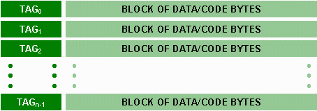
Each block of data is identified with a number called a tag that can be used to figure out what the original main memory addresses of the data were before they were loaded into the cache. This way, when the processor is looking for a piece of data or code (hereafter referred to as a word), it only needs to look at the tags to see if the word is contained in the cache.
The tags and the blocks of words are combined in the cache much like that shown in the figure below:

Remember that each tag uniquely identifies the block of words in its row so that the processor knows what the original addresses of the data and code were.
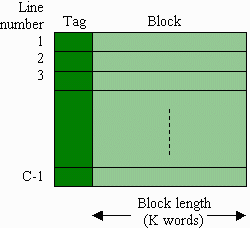
The combination of a tag and the block of words associated with that tag is referred to as a line.
When the processor needs a word from memory, the first place it checks is the cache. The circuits used to access data from main memory may also be activated just in case the data is not found in the cache, often referred to as a "miss". The results from the main memory search will not be used if the word is found in the cache. If the search in the cache was successful, the processor will just use the cache's word and disregard the main memory.
If, however, the cache did not contain the requested word, then one of two operations will happen depending on the processor's design:
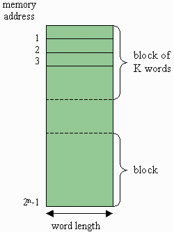
The typical memory simply stores all of its words in sequential addresses. It's interaction with the cache, however, dictates that a block is defined using the addresses going to main memory. Note that this has no effect on the operation or storage of words of main memory; it is only a method for using the main memory addresses to organize words within the cache.
The full main memory address defines a specific memory location within memory. For example, a unique twenty-bit address such as 3E9D116=0011 1110 1001 1101 00012 points to exactly one memory location within the 1 Meg memory space.
If we "hide" the last bit of the address, i.e., it could be a one or a zero, than the resulting address could refer to one of two possible locations, 3E9D116 (0011 1110 1001 1101 00012) or 3E9D016 (0011 1110 1001 1101 00002). If we "hide" the last two bits, then the last two bits could be 00, 01, 10, or 11. Therefore, the address could be referring to one of 4 possible sequential locations:
3E9D016 = 0011 1110 1001 1101 00002
3E9D116 = 0011 1110 1001 1101 00012
3E9D216 = 0011 1110 1001 1101 00102
3E9D316 = 0011 1110 1001 1101 00112
This is how a block is defined. By removing a small group of bits at the end of an address, the resulting block identifier points to a group of memory locations. Every additional bit that is removed doubles the size of the group. This group of memory locations is referred to as a block.
The number of words in a block is defined by the number of bits removed from the end of the address to create the block identifier. For example, when one bit is removed, a block contains two memory locations. When two bits are removed, a block contains four memory locations. In the end, the size of a block, K, is defined by:
K = 2w, where w represents the number of bits "removed"

Remember from our discussion on the organization of a cache, words are stored in a cache as a block, the combination of which defines a line. Therefore, the length of a line in a cache is the size of the tag (which depending on how data is stored in the cache, may be the same as the block identifier) and the number of words in a block multiplied by the word length.

For this simple discussion on caches, only a few of the characteristics of RAM caches will be discussed in detail. The majority of the characteristics will only be described briefly.
The cache system used by a processor is defined by six traits:
As far as the size of the cache is concerned, there is a balancing act that need to be performed to come up with the best cache for the system. First of all, larger caches are more expensive. When it comes to performance, however, larger caches are not necessarily better.
The larger a cache is, the more likely it is that the processor will find a piece of recently used data in the cache. The problem is that as a cache gets larger, the address decoding circuits also get larger and therefore slower. In addition, more complicated logic is required to search a cache because of the seemingly random way that data is stored in it.
There is also a relationship between size of a block and the performance of the cache. As the block size goes up, the possibility of getting a successful "hit" when looking for data could go up due to more words being available. For a fixed cache size, however, as the block size increases, the number of blocks that can be stored in a cache goes down. This makes it so that the number of hits could go down. A typical size of a block is fairly low, between 4 and 8 words.
As was mentioned earlier, a processor system might have two caches: one located in the processor (level 1) and one on the motherboard (level 2). There is a second reason why two caches might appear in a system.
In some cases, a processor will use one cache to store code/instructions only and a second cache to store only data. This is used for special architectures where the processor needs to keep the program separate because it treats those values differently. This method of cache organization is called a split cache.
There are three main methods of determining where to store blocks in the cache so that the processor can quickly find them when it is looking for a word: direct, full associative, and set associative. A detailed description of all of them is beyond the scope of this discussion, but we will introduce the simplest of the three methods, direct.
Assume main memory is divided up into n blocks and the cache has room to contain exactly m blocks. m is much smaller than n because the cache is much smaller than main memory.
If we divide m into n, we should get an integer which represents the number of times that the main memory could fill the cache with different blocks from its contents. For example, if main memory is 128 Meg (227) and the cache is 256 K (218) and a block size is four words (22), then the main memory can contain n = 227-2 = 225 blocks and the cache can contain m = 218-2 = 216 blocks. Therefore, the main memory could fill the cache n/m = 225/216 = 29 = 512 times!
Okay, if you didn't keep up with that discussion, just understand this: the memory is much larger than a cache, so each line in the cache is responsible for storing one of many blocks from main memory. In the case of our example above, each line of the cache is responsible for storing one of 512 different blocks from main memory.
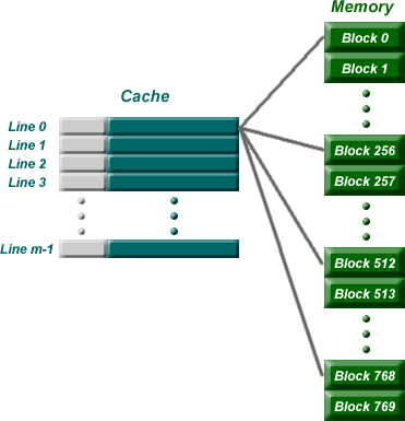
Direct mapping assigns each memory block in main memory to a specific line in the cache. If a line is all ready taken up by a memory block when a new block needs to be loaded, the old block is trashed. The figure below shows how multiple blocks are mapped to the same line in the cache.

As for how this is implemented, remember that a group of bits from the least significant end of an address represent the words in a block. A second group of bits is taken from the least significant end of the remaining bits. This provides the line number from within the cache where the block is to be stored.
For example, if a cache had 210=1024 lines, then a line would need 10 bits to be uniquely identified. Therefore, the next ten bits of the address would indicate where in the cache the data is to be stored. The remaining bits will be the tag.
|
tag
|
bits identifying line in cache
|
word id bits
|
Breakdown of a Memory Address into its Components
Once the block is stored in the line of the cache, the tag is copied to the tag location of the line.
In summary, direct mapping breaks an address into three parts: tag bits, line bits, and word bits. The word bits are the least significant bits and the identify the specific word within a block of memory. The line bits are the next least significant, and they identify what line in the cache the block will be stored in. The remaining most significant bits are stored with the block as the tag and identify where the block of memory is located in main memory.
Assume a cache system has been designed such that a block contains 4 words and the cache has 512 lines (i.e., it can hold up to 512 blocks). What line of the cache is supposed to hold the block that contains the word from the sixteen-bit address 345616? In addition, what is the tag number that will be stored with the bits?
Answer: To begin with, we need to divide the address into the word bits, the line bits, and the tag bits. Since 4=22, then the least two significan bits identify the word within the block. Since the cache has 512=29 lines, then the next 9 bits identify the line number where the data is supposed to be stored in the cache. The remaining bits are the tag bits.
By the way, since the address
|
5 tag bits
|
9 bits identifying line in cache
|
2 word id bits
|
Converting the address to binary gives us 345616 = 0011 0100 0101 01102. That means that the address breaks into the following components.
|
5 tag bits
|
9 bits identifying line in cache
|
2 word id bits
|
|
00110
|
100010101
|
10
|
Therefore, out of the 512 lines of the cache, this block will be stored at line 1000101012 = 27710. The tag that will be associated with this block is 001102.
The first 10 lines of a 256 line cache are shown in the table below. Identify the address of the data that is shaded a darker green and contains d8. For this cache, a block contains 4 words. (Note: The tags are given in binary in the table.)
| Block data | |||||
| Line # | Tag | word 00 | word 01 | word 10 | word 11 |
| 0 | 110101 | 12 | 34 | 56 | 78 |
| 1 | 010101 | 54 | 32 | 6a | d3 |
| 2 | 000111 | 29 | 8c | ed | f3 |
| 3 | 001100 | 33 | a2 | 2c | c8 |
| 4 | 110011 | 9a | bc | d8 | f0 |
| 5 | 001101 | 33 | 44 | 55 | 66 |
| 6 | 010100 | 92 | 84 | 76 | 68 |
| 7 | 000100 | fe | ed | 00 | ed |
| 8 | 100000 | 00 | 11 | 22 | 33 |
| 9 | 101000 | 99 | 88 | 77 | 66 |
Answer: First, we need to do the same thing that we did in the first problem, find the number of bits that represent each part (word, line #, and tag) of the address. From the table, we can see that 2 bits represent the word and 6 bits represent the tag. But what about the line number?
Since the cache has 256=28 lines, then 8 bits represent the line number in the cache. Therefore, the address is divided up as follows:
|
6 tag bits
|
8 bits identifying line in cache
|
2 word id bits
|
The shaded cell in the table has a tag number of 110011. The line number is 4 which in 8 bits of binary is 000001002. Last of all, it is in the third column which means that it is the 102 bit. (Remember to start counting from 0.) Putting all of this information together gives us:
|
6 tag bits
|
8 bits identifying line in cache
|
2 word id bits
|
|
110011
|
00000100
|
10
|
Therefore, the address that the shaded cell containing d8 represents is 1100 1100 0001 00102 = CC1216.
Using the table from Exercise 3, retrieve the data that has an address 101C16.
Answer: First convert the hexadecimal address to binary.
101C16 = 0001 0000 0001 11002
Next, using the breakdown of bits for the tag, line number, and word, break down the binary address.
|
6 tag bits
|
8 bits identifying line in cache
|
2 word id bits
|
|
000100
|
00000111
|
00
|
From this we see that the tag is 000100, the line number is 000001112 = 710, and the word number is 002. Looking at line number 7 we see that the tag is in fact 000100. (Note: If the tag number did not match the tag we calculated, then we know that the cache did not contain our address!) From line number 7, find the word represented by 00 and we get fe.
Using the table from Exercise 3, determine if the data from address 982716is in the cache.
Answer: First convert the hexadecimal address to binary.
982716 = 1001 1000 0010 01112
Next, using the breakdown of bits for the tag, line number, and word, break down the binary address.
|
6 tag bits
|
8 bits identifying line in cache
|
2 word id bits
|
|
100110
|
00001001
|
11
|
From this we see that the tag is 100110, the line number is 000010012 = 92, and the word number is 112. Looking at line number 9 we see that the tag is equal to 101000 which does not equal 100110. Therefore, the data from that address is not contained in this cache and we will have to get it from the main memory.
Created by David L. Tarnoff for exclusive use by sections of CSCI 2150 at ETSU.