
The purpose of this lab is to prove how different representations of a Boolean circuit can have the same truth table. You will do the following:
In last week's lab, you used the two input AND and OR gates provided by LabView. This week's lab will require AND and OR gates with more than two inputs. There is a special gate that does this for us in LabView. (This representation is by no means standard. It is only to be used in your LabView circuits.)
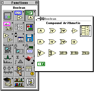
The multiple input gates in LabView are added to your diagram using the compound arithmetic icon (the one in the box in the figure below).

When you first place the icon, it will appear as a two input addition
![]() . To change the number of
inputs, use the mouse to grab one of the corners, and drag the icon
"larger" until you have enough inputs. To change the function (e.g., go
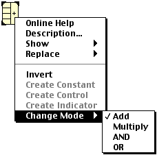
from addition to a logic AND) right-click on the icon, select "Change Mode",
and click on the new function you want the gate to perform. (See the figure
below.)
. To change the number of
inputs, use the mouse to grab one of the corners, and drag the icon
"larger" until you have enough inputs. To change the function (e.g., go
from addition to a logic AND) right-click on the icon, select "Change Mode",
and click on the new function you want the gate to perform. (See the figure
below.)

You can also add inverters at the inputs or the output by right-clicking
on the input or output you want to alter and selecting "invert". This
two-input AND gate has been changed to a NAND gate by adding an inverter
to the output. ![]()
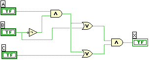
For the first part of this lab, you will build the circuit represented below with the Boolean equation.
Mine looked something like this:

Verify that my circuit is correct, then build and run the circuit using LabView. Develop the truth table by switching the inputs on and off and marking the resulting output. Call me over to verify the truth table before you move on to the next part.
Using the rules on page 167 of our textbook. Reduce the equation from part 2. Once you have reduced the equation, build the new circuit using LabView and verify that it has the same truth table as Part 1.
Using the truth table that you developed from Part 1, create the POS equation. (Product of Sums) Remember that this equation has a sum for every 0 in the truth table. Once you have developed the POS equation, build the new circuit using LabView and verify that it has the same truth table as Part 1.
Using the truth table that you developed from Part 1, create the SOP equation. (Sum of Products) Remember that this equation has a product for every 1 in the truth table. Once you have developed the SOP equation, build the new circuit using LabView and verify that it has the same truth table as Part 1.
Replace ALL of the gates except the inverters with NAND gates. (this means both the ANDs and the OR.) This is easiest to accomplish by right-clicking on each AND and OR gate and selecting replace. From the functions window that pops up, select the NAND gate. Once you have created this new circuit, see how its truth table compares with that of Part 1.
Developed by David Tarnoff for sections of CSCI 2150 at ETSU