The objective of this assignment is to apply our knowledge of Karnaugh Maps to the partial design of a 7-segment display driver.
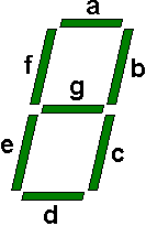
One of the basic display components of digital circuits is the 7-segment display. It has (oddly enough) seven LED segments that are arranged in the pattern of an eight.

Notice that each of the segments is lettered so that we can identify them. Basic seven-segment displays have individual inputs for each of the LEDs.
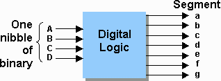
To make a digit appear, the user must know which segments to turn on and which to leave off. In most cases, you can use a seven-segment display driver which takes as its input a four bit number (00002 through 11112) representing the hexadecimal numbers 0 through F. The driver provides as its outputs, the seven control lines needed to turn off or on the LED segments. As a class, we are going to be designing this driver. A block diagram of the system is shown below.
Let's continue our discussion of the seven segment display. To display a 1, we will need to turn on segments b and c and leave the remaining segments off.
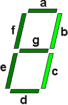
This would be a binary pattern of a=0, b=1, c=1, d=0, e=0, f=0, and g=0. Displaying the number 2 would result in the following:
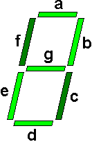
This would be a binary pattern of a=1, b=1, c=0, d=1, e=1, f=0, and g=1.
If we were to work our way through each of the digits, we should be able to fill out the table below. (Note that I've filled out the outputs for 1 and 2.)| Inputs | Outputs | |||||||||
| A | B | C | D | a | b | c | d | e | f | g |
| 0 | 0 | 0 | 0 | |||||||
| 0 | 0 | 0 | 1 | 0 | 1 | 1 | 0 | 0 | 0 | 0 |
| 0 | 0 | 1 | 0 | 1 | 1 | 0 | 1 | 1 | 0 | 1 |
| 0 | 0 | 1 | 1 | |||||||
| 0 | 1 | 0 | 0 | |||||||
| 0 | 1 | 0 | 1 | |||||||
| 0 | 1 | 1 | 0 | |||||||
| 0 | 1 | 1 | 1 | |||||||
| 1 | 0 | 0 | 0 | |||||||
| 1 | 0 | 0 | 1 | |||||||
| 1 | 0 | 1 | 0 | |||||||
| 1 | 0 | 1 | 1 | |||||||
| 1 | 1 | 0 | 0 | |||||||
| 1 | 1 | 0 | 1 | |||||||
| 1 | 1 | 1 | 0 | |||||||
| 1 | 1 | 1 | 1 | |||||||
Begin this exercise by filling in all of the empty cells from the table above. It may help to use the figure below to decide which segments are on for each of the 16 hexadecimal digits.
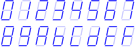
As I stated before, the seven-segment display driver takes as its input the four bits of the hexadecimal number and provides as its outputs the seven lines to drive the LED. Using this information, I want you to solve the following problems based on the segment your group has been assigned.
Developed by David Tarnoff for the Spring 2002 sections of CSCI 2150 at ETSU