
There are a number of issues pertaining to hard disks and their use in computers including the physical interface, configuration of the devices, and the difference between logical and physical devices. This lab is meant to serve as in introduction to these concepts focusing on hard drive identification, configuration, installation, and preparation. This laboratory is more about discussing the concepts than it is about any sort of hands-on exercises. After studying this lab and performing the exercises, the student should be able to:
Over the years, there have been a number of changes in the connection between a motherboard and the hard drives installed in a computer. The original hard drive interfaces were proprietary, i.e., each hard drive had a special interface board for that particular manufacturer. One of the first major advancements was the creation of a standard hard drive interface that allowed computer manufacturers to have a common connection for any hard drive. Since then, most of the advances in hard drive interfacing has been aimed at throughput, i.e., how fast can we transfer data.
The ATA interface, introduced in 1986, was the first successful attempt at standardizing the interface between a motherboard and its hard drives. This interface is also referred to as the Integrated Drive Electronics (IDE) interface. Virtually every PC manufactured during the 1990's and up to the mid-2000's had an IDE interface to pass information back and forth between the motherboard and the higher volume storage devices such as hard drives, CDROMs, and tape drives. It is for this reason that the interface is still being taught in this course.
The term ATA is the original name given to the interface owing to its origin in the IBM AT computer. ATA refers to AT Attachment. ATA interfaces are rarely if ever used to connect to external devices. The definition of the ATA interface describes the standard by which these devices are designed so as to facilitate the communication between them and the motherboard. This definition describes a set of rules such as the timing, electrical interface, and commands that will be used to transmit data.
Standards such as ATA are vital to the way PCs are built and upgraded today. If a component of a computer is based on a well-defined and published standard, than any manufacturer wishing to create the same component could use the standard and the new part could be seamlessly swapped for the old. This is especially important for hard drives as they are a common upgrade.
The ATA interface divides the responsibilities of the hardware quite clearly between the IDE interface card (which is typically incorporated into the motherboard) and the hard drive controller (which is built into the hard drive itself). Back in the old days, the physical hard drive contained very little electronics. There was cable that ran from the drive to a small circuit board that plugged into the motherboard's bus. The small circuit board contained all of the electronics necessary for the processor to store or retrieve data to the hard drive. This arrangement caused a number of problems including but not limited to:
By moving the responsibilities of physically accessing the magnetic media on the platters from the motherboard to a controller card built into the hard drive, a more generic interface could be developed for data transfer. The generic interface that resulted is the ATA/IDE interface. The term Integrated Drive Electronics actually comes from the fact that the electronics for interfacing to the device are integrated into the drive itself.
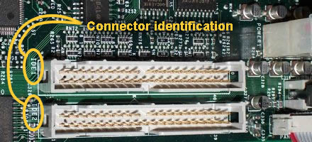
Most of the motherboards you encounter that are ATA-equipped will have one or two 40-pin IDE host adaptors built in. The image below shows two IDE host adaptors side-by-side on a motherboard, one labeled IDE1 and other labeled IDE2. IDE1 is the primary interface. Each interface can handle up to two devices, so a motherboard with two IDE host adaptors can handle up to four drives.
As with all things computer related, advances in technology have allowed the devices we use to improve over time. The definition of IDE has expanded to allow for some of these changes while still allowing older drives to connect to the newer interfaces (backwards compatibility). A brief description of each of these changes is presented below.
All of these standards maintain backwards compatibility, i.e., older drives can be used with the newer interfaces and newer drives can be used on older interfaces.
As was shown in the motherboard lab, the data connection for an IDE interface typically is integrated into the motherboard. There are usually two of these independent interfaces, IDE1 and IDE2, sometimes referred to as the primary and secondary. Each interface (i.e., connector) can support up to two drives. This allows a typical motherboard to control up to four IDE devices.
To connect an ATA hard drive, we need to understand the purpose of each of the connectors on the back of the hard drive. If you look at the back of an ATA drive, you should see an arrangement that looks something like the figure below.
First, the connection for the IDE interface is a 40-pin connector on the back of the hard drive. The pins are spaced 0.1" apart and are in two rows of twenty. The pins are numbered, and typically (but you should verify this before you connect the drive) pin 1 is located nearest the connector for the power. The ribbon cable used to connect the hard drive to the motherboard has a single red wire identifying "pin 1". The power connector also has a red wire. These red wires should be next to each other when connected to a standard hard drive.
Since each IDE interface allows for up to two drives on a single cable, you will need to be able to configure the drives so that one is device 0 and one is device 1. This differentiation allows the motherboard to distinguish between the two drives when attempting to transfer data.
 There are a couple of ways to do this, each of which typically requires a physical modification of the settings on the hard drive itself. Configuring a device as a primary or secondary drive is usually done with a small plastic clip called a jumper. A jumper, the blue block in the figure to the right, is used to straddle two pins on a circuit board to create a "short circuit" or electrical connection that the hard drive controller can detect. The outside of the jumper is plastic, but a metal strip inside of the plastic is what connects the two pins.
Not all hard drives use the same configuration of jumpers to set the device 0/device 1 settings; the documentation that came with your drive or the information printed to the label affixed to the hard drive will outline the specifics for your drive. The most common way, however, will be described here.
Examining the back of your hard drive should reveal six pins situated between the 40-pin IDE connector and the 4-pin power connector. These pins are usually labeled MA, SL, and CS corresponding to device 0 (MAster), device 1 (SLave), and cable select respectively. Placing a jumper so that is connects the two pins labeled MA designates the drive as device 0 while placing a jumper across the pins SL designates it as device 1. If only one drive is on the IDE interface, it should be set to device 0 or CS.
The other option is to use the CS setting. In this case, both drives on the cable must be set to use the CS option. It is the drive's position on the cable that determines whether it is device 0 or device 1. Device 0 is connected to the connector that is at the end of the cable while device 1 is connected to the connector in the middle. When the computer is powered up, a signal is sent down wire number 28 which is only connected to the middle connector. By not receiving this signal, the hard drive at the end understands that it has been assigned to device 0.
A quick note about the IDE cable. The standards that define the IDE interface also define the cable. The basic IDE cable cannot be longer than 18 inches. The middle connector cannot be further than 12 inches from the connector that goes to the motherboard and the last connecter cannot be further than 6 inches from the middle connector. These definitions are used to ensure the electrical characteristics of the connection from the motherboard to the hard drive. Longer cables will cause the data to attenuate or become corrupted by noise before reaching the device or motherboard. The image below shows how the connectors are arranged in this 2/3rd and 1/3rd configuration.
It might make little sense to place the master drive farther away from the processor. One might think that in the name of throughput, a closer drive would be desired. Actually, the problem is that if only one drive exists, and that drive is placed on the center connector, a dangling end would be created past the center connector that had no electrical connection. When current tried to flow down this end, then found no hard drive connected to it, the current would bounce back in what is referred to as a "reflection". This reflection would corrupt the next piece of high-speed data headed down the cable.
Another characteristic of the IDE cable is that some of them have a plastic insert plugging the hole for pin 20. This was originally intended as a "key" to make sure that no one was able to plug the cable in backwards. Pin 20 on the hard drive (which has no assigned purpose) was often cut off to allow this cable to slide on only one way. Now most cables have a plastic key molded into the side of the connector.
The final connection to the hard drive provides power. This is a 4-pin connector with all four pins in a row and a plastic shield around the connector that is about 1" wide and is shaped like a trapezoidal. The shape of the plastic shield prevents the connector from being plugged in upside-down.
There have been a few modifications to the IDE cable over the past few years. First, as was mentioned earlier, with the advent of ATA-4, the IDE cables went to 80 conductors instead of 40. There are still 40 pins on the connectors, but between each of the "used" conductors, an additional conductor is inserted that is connected to ground (a voltage reference that carries no signal). This grounded conductor acts as a shield protecting neighboring devices from each other's signals.
A wire is basically an antenna capable of both transmitting and receiving electromagnetic signals through the air. The higher the frequency, i.e., the higher the speed of data transfer, the stronger the electromagnetic signals become. This condition is called "crosstalk". Electro magnetic signals cannot pass through metal conductors.
The figure below shows how the grounded conductors are protecting or "shielding" the signals radiating from conductor A thereby protecting conductor B from crosstalk.
Another change in IDE cables is the use of colored connectors. Newer IDE cables have a black connector, a gray connector, and a blue connector. The blue connector is to be connected to the motherboard, the gray goes to the device 1, and the black goes to device 0.
Serial ATA was introduced in 2003 as a replacement for ATA (now sometimes referred to as PATA for parallel ATA). The benefits are smaller cabling and faster transfer times. The benefit of the smaller cabling is simple: ribbon cables are wide and block air flow inside of the computer case. By using a serial interface, fewer conductors are needed allowing for a smaller cable and more airflow inside the case. In addition, smaller cables means smaller connectors which provides more space on the motherboard and simpler wiring.
As for the faster rates, remember from our description of crosstalk that the higher the frequency, the worse the transmission of electromagnetic signals. With fewer conductors running next to each other, crosstalk becomes much less of an issue.
SATA only allows for one device per cable. This means that PCs that used to use two IDE interfaces to connect to four drives will need four SATA interfaces to connect to four SATA drives.
SATA also allows for hot swapping, the ability to plug and unplug devices while the system is powered up and running.
A brief description of the changes in the SATA interface is presented below.
To begin with, a basic SATA data cable has 7 conductors: 3 grounds and 4 data lines configured as two pairs. Remember that the ATA/IDE cables are limited to a length of 18 inches. The SATA cables are allowed to be as long as 39 inches (1 meter).
The power cable is 15-pin, but not because there are more levels of power (3.3, 5 and 12 volt are supplied to SATA devices). Each voltage level is supplied on three line in order to provide a higher level of current. The pins and wires are too small to supply enough current by themselves. There are also five conductors supplying ground connections.
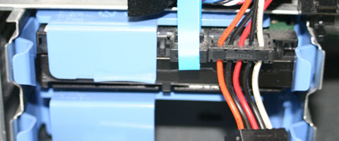
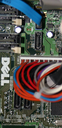
The images below present the SATA connections both at the drive and at the motherboard. The drive picture on the left shows the data cable (the blue cable) going into the connector toward the middle of the drive while the power connector (the one with the orange, black, red, and white wires) goes into the connector on the right. As for the motherboard, typically, there are connections for either 2 or 4 SATA drives. The image on the right shows a motherboard with 4 connectors, two of which are partially hidden beneath the wires for the power connector for the motherboard.
 |
 |
Another interface definition that computers use to communicate to hard drives is the Small Computer System Interface or SCSI. Like ATA, there are a number of variations on the interface definition, but unlike ATA, not all of the interfaces are backwards compatible with earlier drives or controllers.
The first standardization of the interface was SCSI-1. It had an 8-bit wide data bus and a clock speed of 5 MHz. There have been two primary evolutions of the SCSI interface since then, SCSI-2 and SCSI-3, with many sub-variations that defined different speeds and bus widths. The current iteration is the SCSI-3 Ultra 320 which has a 16 bit wide data bus and a clock speed of 80 MHz. This allows for a transfer rate of 320 Megabytes per second. In addition, up to 16 devices may be connected to this interface.
SCSI has better support for multiple drives making it a superior interface for applications such as RAID systems. RAID (Redundant Array of Independent Discs) is a system for using multiple hard drives so that they appear as one. There are different configurations of RAID that are meant to improve performance and reliability. In addition, SCSI can be used as an interface to scanners, CD-ROM/RW drives, printers, and other storage devices. The SCSI interface tends to be more expensive than ATA, and as such tends to be used for high-performance applications such as servers.
Portable data has always been important to users, and the external hard drive is one of the better solutions for moving large amounts of data between machines. USB flash drives, sometimes referred to as thumb drives, operate faster, but are not nearly as cost effective as a hard drive with a USB interface nor do they tend to have the long term storage ability of an external hard drive (barring physical abuse). The major drawbacks of external hard drives is the fact that they are larger and do not sustain physical shock well.
There are a number of interfaces available for external hard drives including Small Computer System Interface (SCSI), Universal Serial Bus (USB), Firewire (IEEE 1394), and Ethernet. The Ethernet devices act more as small network file servers than as conventional hard drives, but just like an external drive, they connect to the computer through one of the computer's ports. In most cases, an external drive simply has a converter that takes the data from one of the serial interfaces such as USB and converts it to a standard hard drive interface such as ATA/IDE or SATA.
Physical hard drives and logical hard drives are two different things. Just because you have one physical hard drive mounted in your PC doesn't mean that you couldn't have more than one hard drive designation. For example, when you look at Windows Explorer, you might see multiple drives listed as C:, D:, E:, etc. even though you may only have a single drive installed in the machine.
Back in the old days, the largest hard drive that the Microsoft Disk Operating System (DOS) could recognize was 85 Megabytes. Not much, huh? So when larger hard drives came out, we needed to have a way to make them accessible to the user for storing program or data files. To do this, a larger drive was divided into smaller hard drives, no one of which was bigger than 85 Meg. This "dividing up" is referred to as partitioning. Still just one physical drive, but now the operating system thought it saw multiple logical drives. This division of the single physical drive was accomplished simply by storing a specific pattern of ones and zeros to the hard drive to designate the end of one partition and the beginning of another.
Each partition has its own file system. There are a number of types of file systems, each of which is generally associated with a specific operating system. For example, the NTFS file system is attributed to Microsoft while the EXT3 file system is attributed to Linux. File systems are generally incompatible although some operating systems such as Linux can read and sometimes write to other operating system file systems.
For example, imagine two people trying to share a filing cabinets. One of them stores everything by the date the document was received and the other stores everything in alphabetical order. Not too bad a problem, right? Well, ask one to find information from the other's filing system in the dark. Well, that's stupid! Not really.
If one operating system interprets the stored binary values differently than the other, they cannot share a common hard drive partition. We will have to create separate partitions if we want to run separate operating systems such as Linux and Windows. In fact, Linux typically uses two different types of partitions by itself for a single installation: one for programs and one for virtual memory storage. In the end, a hard drive running both Linux and Windows will have at least three partitions, one for Windows and two for Linux.
Another benefit of partitions is that you can have your operating system on a single partition and your data on a second partition. If you ever want to reformat the partition where your operating system is in order to reinstall, you can do so without affecting your data. In theory this can protect your data if a virus attacks the operating system.
Partitions cannot share space on a hard disk. Therefore, partitions must be distinct. This should become obvious when setting up partitions on a hard disk.
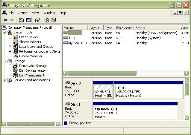
The following is a step-by-step exercise allowing you to examine the partitions on the external drive you purchased for this course.
Note: Deleting a partition permanently removes the data on that drive. Never delete a partition unless you do not want to access any of the information on that drive again.
Now that we've created unpartitioned/unallocated space on our drive, we need to partition it for our use. (A drive is unusable without being partitioned.) At this point, you may set up only one partition or two depending on how many logical drives you wish to have.
You can also format a partition without deleting the partition. Simply right-click on the partition you wish to format, then select "Format..." This will present you with a window much like that from step 5 of the previous sequence. As with deleting a partition, formatting erases all of the data from that partition.
We will be going more into formatting in the Linux lab where you'll need to create multiple partitions for the Linux installation.
There is one more step we need to take to allow us to perform the rest of the hard drive-based labs for this course. The machines in our 491 lab are configured so that you will be logged in as a non-administrator. Because of this, we need to verify that your hard drives are writable by a non-administrator. Many hard drives come from the factory set up to only be written to by an administrator. We need to solve this problem before you come to lab with your hard drives!
Perform the following steps from a machine that you have administrator privileges on. This could be your home machine.
Developed by David Tarnoff for CSCI 2150 -- Computer Organization at ETSU