
CSCI 2150 -- Laboratory Experiment 1
LabView: Digital Logic Gates
This lab has two purposes:
- to support the past week's lectures on digital logic gates and
- to introduce you to the use of LabView.
Welcome to LabView
The LabView software that we will be using has been developed by National Instruments, and it is an icon-based programming language. That means, that instead of programming with words as is the norm, the user programs by dropping an icon onto the screen and "wiring" it to other icons. This makes it the perfect platform for learning to use the logic gates.
To receive hands-on experience with AND, OR, NOT, XOR, NAND, NOR, and XNOR gates, most digital electronics courses use a plastic grid of holes with a pattern of conductors beneath the grid in order to create digital circuits.
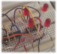
Small ICs (metal-legged plastic chips containing logic gates) can be inserted into this grid, then the metal legs can be connected to the metal legs of other ICs using telephone wire to create a physical realization of a digital circuit. You are missing some opportunities when you don't get to have the experience of wiring the actual digital circuits. For example:
- the opportunity to purchase the ICs, plastic grid (A.K.A. protoboard), power supplies, etc.;
- the opportunity to watch your investment pop and sizzle like a water droplet on a hot iron skillet when you accidentally miswire it;
- the opportunity to learn how easily little pieces of telephone wire break off in the protoboard; and
- the opportunity to spend hours learning how to debug hardware using a logic probe.
LabView allows the user to create these circuits using a control diagram and a user interface that is familiar to any MicroSoft Windows or Mac O/S user without all the messing about with wires, power supplies, and smoke.
Another benefit of using LabView is the highly developed user interface tools. For example, the front panel to the most complex piece of electronic equipment can be developed with simple drag-n-drop components. An interface can be developed with inputs such as switches, buttons, knobs, sliders, text or numeric inputs, etc. Output options also have a wide range including graphs, LED's (little colored lights for lack of a better explanation), text or numeric displays, analog gauges, etc. The panel below is a quick example of what can be designed in just minutes.
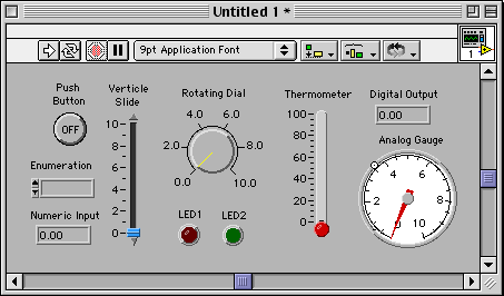
LabView creates what National Instruments refers to as "Virtual Instruments" or VIs. These VIs are "virtual" in the sense that the instrument doesn't really exist, but with the correct hardware, the VI running on the computer operates every bit like a true instrument. A typical VI consists of the panel (the graphical interface that the instrument's user sees) and the control diagram (the program represented with icons wired together.) An example of a control diagram is shown below.

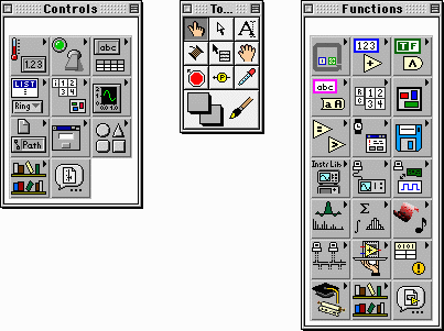
LabView then provides tool palettes that the software designer can use to place panel or control panel components.
Opening a New VI
First, bring up the LabView development environment. The first window you will see prompts you to open a new or existing virtual instrument.
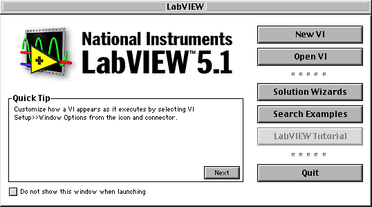
We are going to be creating a new virtual instrument, one that you can use to prove out the logic circuits that we've discussed in class. Therefore, press the "New VI" button. Doing this closes the intro window and displays a number of new windows. They are:
- a blank panel on which you will arrange the VI controls (the user interface),
- a blank diagram on which you will arrange and connect the programming icons,
- a tools pallet which tells LabView what operation you will be performing,
- and either a controls pallet or a functions pallet depending on whether the panel or the diagram is active.
Creating the Panel With the Controls Pallet
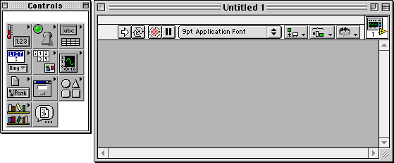
Each one of the buttons on the controls pallet brings up a menu that reveals all of the possible controls or outputs you can place on the panel. Below is the result when you click on the boolean controls.

The first part of this lab will be to prove out the logic
of a two-input AND gate. This means we will need to place two
inputs representing each of the AND gate inputs. Do this now
by selecting one of the input types, placing it on the panel, and
naming it. (Its name appears in a label above the control. If
you happen to click off of the label before you name it, click
on the edit text button,![]() ,
edit the control's name, then click back on the position/size/select
button,
,
edit the control's name, then click back on the position/size/select
button, ![]() )
Repeat for the second input. Note also that the LEDs are
indicators and are used for output, not input.
)
Repeat for the second input. Note also that the LEDs are
indicators and are used for output, not input.
After I did this, this is what my panel looked like. I just happened to pick the labeled oblong buttons for my inputs.

Next, place an output on the panel. This would be like an LED.

Creating the Diagram With the Functions Pallet
Now, our user interface, simple as it may seem, is complete. Now it is time to turn our attention to programming the bits that will control this interface. Click on the diagram window. You should see that your inputs and outputs have been placed on this window. Use the mouse to arrange them to your liking.

Now, we can connect the inputs and outputs with our logic. From the boolean function button, select the gate that you need to begin your logic diagram with.

Note, all of the gates are 2-input gates. Later in the lab, we will be creating 3-input gates from 2-input gates. To do this, just cascade multiple 2-input gates for your equations with more than two inputs. For example:

Don't worry about proving it here. We will get to that later in this lab. Now, back to the diagram.
Once you've placed a component, you should see that the
run button has become broken, ![]() ,
indicating that there are problems with the program. Once
you've correctly wired the diagram, the run button should
become whole again,
,
indicating that there are problems with the program. Once
you've correctly wired the diagram, the run button should
become whole again, ![]() ,
allowing you to run the instrument.
,
allowing you to run the instrument.
You may now connect the components to your inputs, outputs,
and other gates using the connect wire tool, ![]() .
Connect the components just as you would draw lines between
components on your paper diagram.
.
Connect the components just as you would draw lines between
components on your paper diagram.

Hint: There are a number of things you can do to make this lab far more difficult than it has to be. All of them involve shorting the "wires" together. To ensure that you are connecting the wires correctly, note that when the wiring tool is over the item it will connect to, the item's input blinks. (See the figure below.) For the two input gates, you need to make sure that you are not connecting both wires to the same input.

Running the Instrument
Once you've finished wiring the diagram, the run button
unbroken be whole again. To test your circuit, press the
run continuously button, ![]() ,
either from the diagram or the panel windows. To stop it,
press the abort execution button,
,
either from the diagram or the panel windows. To stop it,
press the abort execution button, ![]() .
.
Hint: If you cannot find why the diagram still has errors, i.e., the run button is "broken", press the broken run button and it will reveal the errors to you.
Once your VI is running, call me over to verify it.
Create and Verify the Three-Input AND Gate
Using LabView, construct the circuit shown earlier in this document where two 2-input AND gates are used to create a 3-input AND gate. Once you've created it, verify the truth table for the 3-input AND gate. Last of all, call me over to verify the circuit's operation.
Create and Verify the Four-Input OR Gate
Using LabView, construct and verify the truth table for the 4-input OR gate. Remember, the output of the OR gate is a logic 1 when one or more of the inputs are a logic 1. Call me over to verify the circuit's operation.
Developed by David Tarnoff for the Fall 2001 sections of CSCI 2150 at ETSU