
This document is not a step-by-step instruction manual for the motherboard experiment, rather it is a reference for material you will be responsible for on the quiz given during the next class period. As far as the motherboard experiment goes, I will be leading you through the installation of the equipment during class.
If you miss this lab or if you weren't able to get your PC up and running, please contact me regarding how to make up the lab. Most likely, you will be coming in during my office hours so we can reassemble a computer.
During this lab procedure, you will come into direct contact with circuit components. Remember to follow all procedures to avoid static discharge that may damage these sensitive components. If you do not remember these procedures, please see the PC configuration lab instructions. If you or your lab partner are found not following anti-static procedures during any portion of the lab, you will automatically forfeit 10% (one letter grade) of your motherboard lab quiz grade.
For every connector on a PC, there is only one way it should be plugged in. (Notice I said "should be" and not "can be".) Some of these connectors are "keyed" so that they only fit one way, but some of them are not. For the ones that are not, you must learn the method to identify the correct orientation before installing the connector. If you plug one of them in backwards, you could cause physical or electrical damage to the device. Therefore, it is critical that you know how to plug them in correctly.
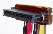
The majority of the cables you will be using are ribbon cables. These cables group the wires together in flat ribbons with connectors crimped at either end and possibly in the middle.
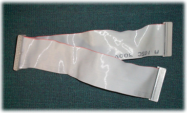
Typical Ribbon Cable
Each of these ribbon cables designates a primary pin, pin 1, by coloring or marking the cable somehow. Usually, it is colored red. Sometimes the connector is marked too. It might have a small triangle etched into the plastic of the connector indicating pin 1.
As for what you are plugging the connector into, the pins on a motherboard or device should have a pin 1 indication too. Typical indicators are:
As long as you follow the practice of always lining pin 1 of the cables to pin 1 of the connectors, the devices will be connected properly.
It is extremely easy to break or bend the pins that connect these devices together. Please take extreme care when connecting or disconnecting these devices. This includes pulling connectors off straight rather than at an angle or by prying one side up at a time. It also means that you shouldn't force connectors together. If your connector pins are bent, try gently straightening them with a small set of pliers before connecting your device to them.
Power supplies typically look like a rat's nest of wires. These wires are separated into two main groups: motherboard power connections and peripheral power connections.
To begin with, the motherboard requires multiple levels of voltage and multiple sources for proper operation. Therefore, the connectors to the motherboard tend to appear complex. The figures below show the two main types of motherboard power connections that you will see.
Older AT Power Supply Connections for a Motherboard
Source: Beeson, Dan L., Assembling and Repairing Personal Computers,
Prentice Hall, Upper Saddle River, NJ, 2000, p. 33.
Newer ATX Power Supply Connections for a Motherboard
Source: Beeson, Dan L., Assembling and Repairing Personal Computers,
Prentice Hall, Upper Saddle River, NJ, 2000, p. 33.
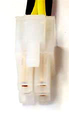 Sometimes, the second, smaller connector (the auxilliary power connector) shown in the diagram for the newer ATX power supplies is slightly different. For example, the motherboard power supplies for our Dells use a four-pin secondary power connector that looks like that shown in the figure to the right. It is connected to the motherboard through a connector that is close to the processor toward the rear of the machine. It is hard to get to requiring that the wires pass beneath the processor cooling fan.
It is particularly easy to destroy a processor with the older AT-type power supplies by connecting the power connections wrong. As shown in the diagram, there are two flat, white connectors with six wires going into them. These are the wires that provide power to the motherboard. They connect in a line to connectors on the motherboard. Note: These connectors can easily be swapped as they are not keyed. The motherboard will be ruined if this happens! Make sure to plug them in so that the black wires of both connectors are next to each other. If you are unsure, ask before plugging them in.
As for the rest of the wires coming out of the power supply, these provide voltage to the peripheral devices installed inside the PC's housing. These include hard drives, floppy drives, CDROMs, and other storage devices. Each of these connectors has four wires: two providing a ground or 0 volt connection, one for 5 volts, and one for 12 volts. There are two styles of this type of connector: a smaller (about 1/2" wide) white connector that provides power to the floppy disk drive and larger (about 1" wide) connectors that go to all other devices. The latter has a trapezoidal shape when viewed from the end.
 Non-SATA Device Power Connector |
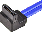
 SATA Power Connector |
 Floppy Power Connector |
In this exercise, your lab computer will be disassembled, all that is except the motherboard. The motherboard is the large printed circuit board that is mounted to the bottom of the computer's case. Motherboards have standard mounting holes so that the same computer case can be used with different boards.
All of the components of a computer system are connected in some way to the motherboard. It is those connections that this lab is meant to show. In the end, you should be able to connect any device to the motherboard or even swap motherboards. To upgrade a computer's motherboard, simply disconnect all of the peripherals, unmount the old motherboard, mount the new motherboard, and reconnect the peripherals.
The image below is a typical motherboard, the Intel D865GBF along with the documentation showing the positions of the board's components.
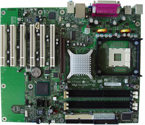
Top View of a Motherboard
Diagram of Motherboard's Components
There are two connections for the floppy drive:
Most older hard drives, CDROMs, CD-R/Ws, and some other internal devices such as ZIPTM and JazzTM drives use a cable configuration called an IDE interface. Like the floppy cable, this is a single cable with three connectors on it. Unlike the floppy cable, it is a 40-pin cable and it does not have a twist in it. One of these connectors plugs into the 40-pin IDE controller connector found on the motherboard. (It might also be connected to a plug-in adaptor card on very old machines.) Each of the other two connectors can be connected to a drive.
Since a single IDE cable allows for up to two drives, there must be a method for the drives to be distinguished from one another. Using hardware on the back of the hard drive, each drive can be configured as either the primary drive or the secondary drive. Most PCs have two connections on the motherboard for IDE interfaces. This means that the typical PC can have up to 4 IDE devices.
Configuration is usually done with a small device called a jumper. As discussed in the BIOS configuration lab, a jumper (the blue block in the figure below) is used to straddle two pins on a circuit board to create a "short circuit" or electrical connection. The outside of the jumper is plastic, but a metal strip inside of the plastic is what connects the two pins.
Older hard drives had the user place a jumper across the MA pins (one of three vertical pairs of pins sitting between the IDE connector and the power connector) to configure it as the primary drive. Placing a jumper across the pins labeled SL made it the secondary drive. If only one drive is on the IDE interface, it should be configured as the primary drive. The third pair of pins on the back of the drive used for configuration were labeled CS for "cable select". Newer BIOSs prefer the use of cable select to configure the primary and the secondary drives.
Newer hard drives do not use the standard MA, SL, and CS jumper settings. Please read the documentation that came with your hard drive or see the settings description found on the hard drive's case to determine how to set the drive as a primary or secondary drive.
The lab's motherboards have a single IDE interfaces allowing for a total of up to two drives. If you wish to boot from a hard drive connected to this interface, generally you want to connect it as drive 0 on the primary IDE interface. The primary IDE interface is usually labeled IDE1.
Remember to observe the pin 1 orientation of the cable. If there is no marking on the drive as to which pin on the 40-pin IDE cable is pin 1, then assume it is the pin closest to the power supply connection.
Lastly, each drive needs to have one of the power connectors from the power supply connected to the power input on the back of the drive. Select one of the larger 4-pin connectors (the one with the trapezoidal cross-section) and insert it into the back of the drive.
Since only one device is allowed to be connected to a single SATA bus, the installation of these devices is quite simple. All that needs to be done is to connect the data cable and the power cable.
 The power connection from the power supply is unique to the SATA drives and does not look like any of the other power connectors. It alone has five wires coming from it and the connector is a slot with small electrical pads inside where a circuit board can be inserted instead of larger holes where pins can go. On the back of the hard drive, you should see two connectors that are simply rows of gold electrical pads. The wider of these connectors with 15 pads is where the power supply is to be connected. The connector is keyed so that there is only one way to insert it.
 The SATA data cable has slightly smaller connections than the power connector. The same connector is on the motherboard and the back of the hard drive, so there should not be any confusion about connecting this connector. On the back of the hard drive, next to the power connector, you should see the second connector. This one has only 7 pads. Once again, the connector is keyed so that there is only one way to insert it.
Memory has gone through many iterations over the past 20 years. The first ones used in PCs where individual chips with two rows of pins that were inserted into sockets on the motherboard. But as has been revealed during our study of interfacing memory to the microprocessor, if we are to use larger memories, then we need more address lines. In addition, increases in the number of bits being stored per memory location requires more data lines. Therefore, the memory devices have required more and more pins to be connected to the processor. The table and figure below give a quick look at the development of PC memory.
| Memory Term | Number of pins | Sizes | Comments |
| Dual Inline Package (DIP) | Approx. 24 to 32 | 1K to 32K | Very old technology (pre 1990's). Memory chips plugged directly into sockets on the motherboard. |
| Single Inline Pin Package (SIPP) | 30 pins | 256K to 16Meg | A single line of pins running along the edge of the memory board were to be inserted into a socket on the motherboard. Problems occurred often with pins bending or breaking during installation. |
| Single Inline Memory Modules (SIMM) | 30 or 72 pins | 4-32Meg | Solved the SIPP problem by taking off the pins and making a connector that the memory stick "clipped" into. The pads that used to be soldered to the pins of the SIPP became the connection to the socket on the motherboard. Pads on opposite sides of the memory stick were duplicates of one another. |
| Dual Inline Memory Module (DIMM) | 168 or 200 pins | 32-256Meg | Increased the capacity of the SIMM by disconnecting pads on opposite sides of the memory stick thereby doubling the number of connections to the motherboard. Also increased the length of the memory stick to increase the number of connections. |
There are two types of modern memories: SIMMs and DIMMs. Both plug into the motherboard in long, low connectors with "fingers" at each end to hold the memory sticks after they've been installed. Both are also "keyed" so that there is one way to install them onto the motherboard.
The SIMMs (the older of the two) slide into the connectors, then tilt back until they click into place. If they don't click, don't force it. They are keyed so that they fit snuggly into the connectors only one way. Try to turn them around and see if they work any better the other way.
DIMMs slide straight down into the connectors following vertical channels or guides that support the sides of the memory stick. Once the memory stick is seated properly in the connector, a lever at either end holds the memory in place. To release the memory, push the lever away from the memory card and the memory stick will eject. These are the type used in our lab PCs.
Usually, the memory connectors/slots on the motherboard are numbered. Almost every motherboard must have memory installed beginning in the lowest numbered slot. Some SIMM slots also are set up so that you can only physically get to some of the slots if other slots are empty. If there are no numbers, assume that the memory is to be installed beginning with the slots closest to the processor.
During the course of this lab, there will be no need to remove or install a processor. For the sake of instruction, however, it would be nice to at least show you how it is done.
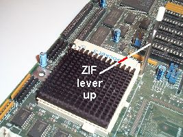
Older processors use what is called a Zero Insertion Force (ZIF) socket. These sockets use a lever to grasp the pins of the processor to hold it in its socket.
To remove a processor, first locate the ZIF lever.
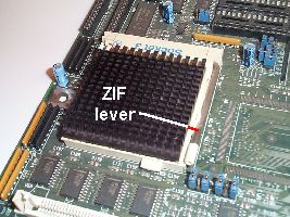
Raising the ZIF lever will release the pins of the processor.
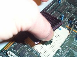
Now you should be able to pull the processor straight out from its socket. If you do this, be sure to note the orientation of the processor. Some motherboards do not give very good pin 1 references for the processor thereby making it difficult to reinsert the processor with the correct orientation.
Newer processors are attached much like a plug-in circuit board. A long edge connector inserts into a socket on the motherboard. These processors have screws on either side that pull the processor's connector tightly against the motherboard's connector.
In order to test your installation of the motherboard devices, we need to have some basic I/O installed. There are two round connectors pointing off the back of the motherboard with 6 sockets for pins a a slot in the center. These connectors allow for a PS/2 type keyboard and mouse to be attached to the motherboard. Usually, there is printing on the motherboard to indicate which connector goes to the mouse and which goes to the keyboard.
The mouse and the keyboard provide input to the motherboard, but we will also need output. VGA monitors are connected to the motherboard using a DB15 connector, a fifteen-pin connector (3 rows of 5 pins) that is shaped like a tall, skinny "D" laying on its side. Connect the monitor to this connector.
Developed by David Tarnoff exclusively for use by CSCI 2150 students at ETSU