
There are two basic objectives behind the accomplishment of this laboratory experiment:
Hardware is a large part of the embedded system design process. Not only is hardware a necessity in order to have an end product, but it is also necessary in order to have something to develop and test the software on.
The development of electronic circuitry usually begins in CADD, then moves to simulation software for verification, then to a printed circuit board (PCB) design tool, the designs of which are then sent to a circuit board manufacturer, and finally the PCB is populated with the electronic components.
This is a very long and expensive process to go through before the first piece of hardware can have software running on it. There are a number of ways to make this process more reliable in addition to having a temporary hardware setup to use until the final circuit boards are completed. One of the oldest and most common methods is to prototype the circuit using an electronic protoboard.
Most all electronic components and integrated circuits (ICs) are available in a package form referred to as a Dual In-Line Package or DIP. These small plastic chips offer access to the IC's internal components through thin metal legs.

Connecting the metal legs of these chips with other metal legs from the same chip, additional chips, or electronic components such as resistors is what allows us to create simple circuits.
To connect the inputs and outputs of ICs together, a socketed plastic board called a protoboard was developed. This board has rows and columns of holes that allow ICs and short wire leads to be plugged in. A generic protoboard is shown in the image below.
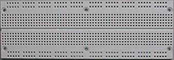
Image Source: Department of Electrical & Computer Engineering
at University of Illinois at Urbana-Champaign
There is a pattern of metal connections between some of the holes on this protoboard allowing us to connect chips to each other and to power and ground. The figure below shows how that pattern is set up.
This allows us to insert an IC so that it straddles the gap running along the center of the protoboard, and connect each pin with wires to other sockets on the protoboard. The rows (denoted X and Y on the previous image) can be used to connect power (Vcc) and ground (GND) to. Some protoboards such as the one in the first image actually have a break in the middle of the X and Y rows so that multiple voltage levels can be connected to the long horizontal runs. The graphic below shows circuit of one chip wired using the protoboard.
There will be no ICs used for this lab, but if and when ICs are used, they should be inserted as shown in the previous graphic.
Unfortunately, measuring the electrical characteristics is not as easy as simply licking your fingers and pinching a bare wire. Electronics are needed to measure electronics.
There are three pieces of equipment used to measure the three basic characteristics of electricity: ammeters measure electric current, voltmeters measure voltage, and ohmmeters measure resistance. Each of these meters measure values using two probes, typically one red and one black signifying positive and negative potentials respectively. These probes have metal tips which need to be inserted into the circuit where the measurements are to be taken.
Ammeters measure current by forcing all of the current passing through a branch of a circuit through the meter. This is done by placing the meter in series with the measured branch. The figure below shows how this is done.
A voltmeter measures a difference in potential or voltage, i.e., the difference in pressure, between two points on the circuit. Therefore, the circuit remains in tact while the voltmeter straddles the section of circuit where the measurement is made. The figure below shows how this is done.
An ohmmeter measures the resistance of a component. The key to measuring resistance is that there must be no movement of electrons within the component or circuit section while the measurement is being performed. Therefore, the power must be disconnected. In addition, if the circuit section to be measured is part of a larger, more complex circuit, it is very likely that the measurement will be affected by other circuit components. Therefore, it is best to measure resistance with the component removed from the circuit.
Typically, our use of an ohmmeter will be to check for
direct connections of 0 ![]() (commonly referred to as a short circuit)
or an open connection of infinite
(commonly referred to as a short circuit)
or an open connection of infinite ![]() (commonly referred to as an open circuit).
(commonly referred to as an open circuit).
These three meters usually come combined in a single package called a multimeter. Multimeters measure voltage for both AC and DC circuits, current for both AC and DC circuits, and resistance. Below is pictured a typical digital multimeter capable of measuring these values and displaying the results on a digital display.
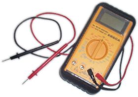
The multimeter typically has a rotary control knob on the front of the unit which dictates which of the electrical measurements will be displayed on its front panel.
Before connecting the probes of the meter to the circuit component for measurement, select the type of measurement along with the maximum value using the control knob. For example, if we are measuring a DC voltage that we think is around 12 volts, but won't exceed 20 volts, turn to the DC 20 V position on the meter. If you are unsure of the specific value, begin with the largest setting and work your way down.
The first experiment that we are going to do is a simple verification of Ohm's Law. Ohm's law is the law that states that the amount of current flowing through a resistor is equal to the voltage across that resistor divided by the resistance.
| I = | V |
| R |
To do this, we are going to create the most simple electronic circuit there is, a resistor across a voltage. This circuit is shown below with a value of 10,000 Ohms for the resistance.
Before we measure the current in the resistor, use Ohm's Law to predict the amount of current that you will find.
To measure current, the conductor through which the current is flowing must be broken and a measuring device must be inserted between the break.
Exercise 1:Begin creating the circuit by connecting power to the protoboard. Select one of the long horizontal rows of sockets in the protoboard to be positive and insert a conductor from the positive output of the power supply into one of the sockets in this row. Do the same for a different row of sockets for the negative connection to the power supply. For the remainder of the lab, these two connections will not need to be changed.
Next, select a 10 KOhm resistor, and insert the legs into the protoboard so that the resistor straddles the gap running along the center of the protoboard. The 10 KOhm resistor has the stripe sequence brown-black-orange. (Brown=1, Black=0, and Orange=3 indicates 10x103 Ohms.)
To connect the resistor to ground, insert a short piece of wire into one of the sockets in the row you designated as ground, then insert the other end into one of the sockets in the same column of sockets connected to the nearest leg of the resistor.
To make a complete circuit, we would make a similar connection between the other end of the resistor and the positive row of sockets. We do not want to make this connection though because we are going to use the ammeter to complete the circuit.
As described in the section on measurements, set the dial on the multimeter to a suitable range for measuring DC current (amps). Touch the red probe to a bare segment of the conductor coming from the positive output of the power supply while simultaneously touching the black probe to the side of the resistor not connected to ground.
The display on the multimeter should read a value close to the value of current you calculated from Ohm's Law.
The typical computer circuit does not have a range of voltage levels. Instead, each conductor contains a binary signal, a one or a zero. Traditionally, a voltage of 5 volts represents a binary one while a ground or 0 volts represents a binary zero. This is not always the case though. RS232 for example uses -12 volts for a binary one and +12 volts for a binary zero. This unusual representation supports the transmission of data over long distances.
A multimeter is unnecessary to measure binary values. All that is needed to measure the signals of a digital circuit is a simple device that indicates whether the voltage for a binary one or a binary zero is present. This device is called a logic probe.
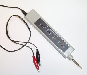
The basic form of a logic probe includes a metallic tip that is placed on the portion of the circuit to be measured and a pair of wires to be connected to a power supply. Typically, the red clip of the power supply connections is connected to 5 volts and the black clip is connected to ground. As for the controls and indicators on the probe body, the typical logic probe combines some or all of the following:
It is important to note the input pins of microprocessors are high impedance. This means that if you were to place an ohmmeter at the input, it would measure near infinite resistance. From ohm's law, we see that this means that almost no current can flow through this input when a voltage is placed across it. This allows the microprocessor to read an input value while drawing a negligible amount of current. This is ideal since a substantial current draw by the microprocessor could change the voltage level at its input. In embedded system design, this would be a problem as it might result in erroneous input.
The figure below presents a generic switch design for a single input using pull-up resistors.
As stated earlier, the current into the microprocessor input, iM, is negligible, and so the only way for the current through the resistor, iR, to flow is through the switch. Therefore, when the switch is open, iR = 0 because no current can flow through an open switch or into the microprocessor. Using Ohm's Law, this means that the voltage across the resistor is:
Vresistor = iR * 10 KOhms
Vresistor = 0 amps * 10 KOhms
Vresistor = 0 volts
Remember that Kirchhoff's voltage law says that the sum of the voltages across loads must equal the sum of the voltages from sources. Since our voltage source is 5 volts and there is no voltage drop across the resistor, then the full 5 volts must drop across the open switch. Therefore, the voltage input to the microprocessor must be 5 volts which is read as a binary '1'.

If the switch closes, the input to the microprocessor is shorted to ground making its input a binary '0'.
Exercise 2:Wire the generic switch circuit using a 10 KOhm resistor and the small push button switch. Use the logic probe to verify the circuit's operation. Remember that if the switch is open (push button up), the logic value input should be '1', and if the switch is close (push button pressed), the logic value input should be '0'.
The typical digital output is an LED. These indicators are small solid state lights that glow only if current is sent into the device in a specific direction. If current isn't flowing or is trying to flow in the opposite direction from that which is specified, the LED will not light. These LEDs can be driven by a digital output from the microprocessor. The figure below presents the schematic symbol of an LED. Current is supposed to flow in the direction that the triangle is pointing.

An LED will turn on only when a current of about 15 mA passes through it from node A to node B. When this occurs, there will be a voltage drop anywhere from 0.7 V to 2.0 V across the LEDs terminals. If more current passes through the LED, it will fail catastrophically in a small puff of very foul smoke.
Since the output voltage from the microprocessor is 5 volts and 5 volts will burn up the LED, we will need resistor in series with the LED to limit the current.
The circuit above assumes a 5 volt supply, therefore, if the LED can only handle 1.3 volts, 5 - 1.3 = 3.7 volts must be dropped across the resistor.
With this information, along with the fact that the LED can only handle 15 mA = 15 x 10-3, we can figure out what resistor is needed using Ohm's Law. Do the calculation now.
To control the LED, a microprocessor's output replaces the ground connection and turns the LED on and off by "turning ground on and off". If the output of the microprocessor is 0 V, binary '0', it will act as a ground and pull current through the circuit turning on the LED. A 5 V output, binary '1', will then turn off the LED because there will be no drop in potential across the series circuit.
Setting the output from the microprocessor to 0 V is called sinking the current. Instead of having the processor supply all the current to turn on the LED, the processor simply absorbs the current and lets the power supply do all of the work. This is the preferred method of output to a device since most microprocessors have a maximum output current rating in the order of 10's or milliamps.
Exercise 3: Wire the circuit below where the microprocessor's output is simulated with a push button. What microprocessor output values does the button simulate for the released position? The depressed position?
![]()
One of the most common ways to measure position is with a potentiometer. A potentiometer is a long resistor (going from A to B in the figure below) that has a wiper (C in the figure) that connects to the surface of the resistor. As the distance between C and one of the end points shortens, the resistance between C and the end point drops. If the distance increases, the resistance between C and the end point increases.

Let's take a closer look at what is happening. First, the total resistance from point A to point B (we'll just call it RAB) can be calculated from the equation presented during our electronics discussion:
|
RAB = |
length from A to B |
| area |
where length is the length of
the conductor, area is the cross-sectional
area, and
![]() is the resistivity of the resistor.
is the resistivity of the resistor.
The resistance between A and C can be calculated in a similar manner. In fact, the resistivity and the cross-sectional area should remain constant. Only the length should change.
|
RAC = |
length from A to C |
| area |
If C is at the midpoint of the resistor, then:
|
RAC = |
½(length from A to B) |
| area | |
| RAC = | ½ * RAB |
Careful examination shows that RAC is to RAB as the distance from A to C is to the distance from A to B. In other words, the change in resistance between points A and C is linear with the change in distance between points A and C.
If a current is running through the resistor from A to B, then a voltage drop will be present across the resistor. The voltage drop from A to C can be calculated with Ohm's law.
VAC = I * RAC
Keeping the current constant, we find that the voltage varies linearly with the position of C. Therefore, a microprocessor monitoring the voltage drop from A to C can determine the position of the potentiometer.
Potentiometers come in a variety of forms too. There are linear potentiometers where the position of C is changed with a sliding lever. There are also rotary potentiometers where turning a knob changes C's position. These are found on volume controls in addition to being used to determine the position of a shaft on a DC motor.
Exercise 4:Wire the potentiometer circuit shown in the figure below. Use the voltmeter to measure the voltage from point A to point C, from point C to point B, and from point A to point B. Verify that the sum of the voltages from A to C and from C to B equals the voltage from A to B. Adjust the potentiometer with the voltmeter probe measuring the voltage from C to either A or B and see how the voltage changes.
Developed by David Tarnoff for the Summer 2003 section of CSCI 4956-011 at ETSU