Although the set of notes you have requested is presented below, it has not been maintained since January, 2003. All of the information in these notes has been included in an on-line text titled Computer Organization and Design Fundamentals. The book is available in three formats, two of which are free electronic downloads. Please visit one of the following links in order to access the format you prefer.
Thank you for your interest in this textbook. Please feel free to e-mail me at tarnoff etsu.edu if you have any questions or comments.
-Dave Tarnoff
Reading: Floyd, Sections 4.1 through 4.2
What ways do we currently have to represent a logic circuit?
Schematic Diagram
Truth Table
|
X | ||||||||||||||||||||||||||||||||
|
|
These two methods are inadequate for a number of reasons:
We need a way to describe circuits that overcomes these annoyances: Boolean Expressions. Using these boolean expressions, we can describe complex digital circuits with mathematical-like equations. These expressions can then be used to quickly evaluate the output of a circuit. And just like Algebra, rules can be applied to these boolean expressions to dramatically simplify them. A simpler equation results in fewer logic gates needed to realize a circuit. This will:
A Boolean expression looks a great deal like an algebraic expression. The circuit inputs are represented by capital letters A, B, C, etc. (Hopefully we won't get past F. That would be 64 possible combinations of 1's and 0's!) The outputs are represented by capital letters X, Y, or Z. (Once again, hopefully we won't need more.) Below, I have shown the boolean expressions that represent each of the three primary logic functions: NOT, AND, and OR.
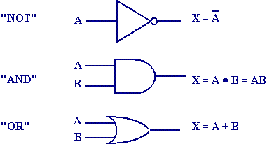
The "NOT" operation may be used to invert the result of a larger expression.
This is then equivalent to the following truth table. (Note that the second column from the right is an intermediate step.)
| A | B | A + B | ^(A + B) |
| 0 | 0 | 0 | 1 |
| 0 | 1 | 1 | 0 |
| 1 | 0 | 1 | 0 |
| 1 | 1 | 1 | 0 |
Another point of note is that since drawing a bar is difficult using HTML, you may see the "NOT" operation represented with a carrot, "^", as in the examples X = ^A or X = ^(A + B).
The operators ·, +, and ^ (the "NOT" bar) may be combined to create more complex equations. (The XOR function (exclusive-or) is typically represented with its AND/OR equivalent of ^A·B + A·^B).
Let's begin with some simple examples. Can you determine the output of the following equations?
1 + 0 + 1 = ?
This equation represents the following circuit.
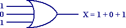
We know that an OR-gate operates under the assumption that if any of its inputs equal 1, then the output equals 1.
1 + 0 + 1 = 1
The generic representation of this gate with inputs A, B, and C has the equation:
X = A + B + C
What if we make this equation just a bit more complicated by adding an inverter to the output of the OR-gate.
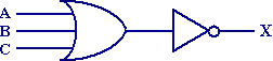
This would have the effect of inverting (NOT-ing) the output of the OR-gate. The boolean representation of this would be:
X = ^(A + B + C)
or using the NOT bar representation:
        ___________

    X = (A + B + C)
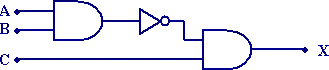
Now, what if we replace the input C with the output of an AND gate making for a more complex combination of logic?
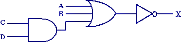
Similarly, this would replace the input C in our equation with the output of the AND gate, C · D.
        _________________

    X = (A + B + (C · D))
It is important to note the use of the parenthesis when putting these boolean expressions together. There is, however, also an order of precedence with an absence of parenthesis. NOT takes precedence over AND which takes precedence over OR. These are true unless overridden by parenthesis. For example:
In the example above, the order of operations is represented by the numbers in the figure below:
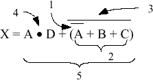
The steps of the process are as follows:
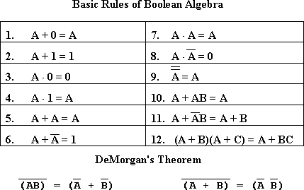
Other rules from Algebra are applicable for boolean arithmetic.
Last of all, we will be proving and applying the following equations during class. (They're a bit much to prove and apply using the limited capabilities of HTML.)
Copyright 2001 by David L. Tarnoff. All rights reserved.