Although the set of notes you have requested is presented below, it has not been maintained since January, 2003. All of the information in these notes has been included in an on-line text titled Computer Organization and Design Fundamentals. The book is available in three formats, two of which are free electronic downloads. Please visit one of the following links in order to access the format you prefer.
Thank you for your interest in this textbook. Please feel free to e-mail me at tarnoff etsu.edu if you have any questions or comments.
-Dave Tarnoff
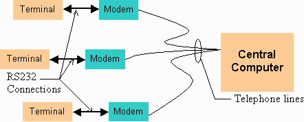
A serial interface, known by the standard that defines it as RS232, is a primitive method of communication between two processors. One of these two processors is labeled the Data Terminal Equipment (DTE) while the other is the Data Communications Equipment (DCE). This harkens back to the days when the serial device was used to connect a dumb terminal (a simple keyboard with a monitor) to a central computer through a modem.

The dumb terminal was capable of only two things, displaying text received from the central computer through the modem or sending text typed on the keyboard through the modem to the central computer: two-way communication of text. To perform this operation, the RS232 communications standard was defined to allow the transmission of text from the terminal (DTE) to the modem (DCE) one character at a time.
As with all the digital operations we've discussed up to now, the computers will only understand binary data. Therefore, each character that can be typed on a keyboard has been assigned a 7-bit binary value. These values are referred to as their ASCII values. The table below shows the original ASCII values from decimal 32 to 126. (The other values are used for control.)
| ASCII | Char | ASCII | Char | ASCII | Char | ASCII | Char | ASCII | Char | ASCII | Char |
| 32 | space | 33 | ! | 34 | " | 35 | # | 36 | $ | 37 | % |
| 38 | & | 39 | ' | 40 | ( | 41 | ) | 42 | * | 43 | + |
| 44 | , | 45 | - | 46 | . | 47 | / | 48 | 0 | 49 | 1 |
| 50 | 2 | 51 | 3 | 52 | 4 | 53 | 5 | 54 | 6 | 55 | 7 |
| 56 | 8 | 57 | 9 | 58 | : | 59 | ; | 60 | < | 61 | = |
| 62 | > | 63 | ? | 64 | @ | 65 | A | 66 | B | 67 | C |
| 68 | D | 69 | E | 70 | F | 71 | G | 72 | H | 73 | I |
| 74 | J | 75 | K | 76 | L | 77 | M | 78 | N | 79 | O |
| 80 | P | 81 | Q | 82 | R | 83 | S | 84 | T | 85 | U |
| 86 | V | 87 | W | 88 | X | 89 | Y | 90 | Z | 91 | [ |
| 92 | \ | 93 | ] | 94 | ^ | 95 | _ | 96 | ` | 97 | a |
| 98 | b | 99 | c | 100 | d | 101 | e | 102 | f | 103 | g |
| 104 | h | 105 | i | 106 | j | 107 | k | 108 | l | 109 | m |
| 110 | n | 111 | o | 112 | p | 113 | q | 114 | r | 115 | s |
| 116 | t | 117 | u | 118 | v | 119 | w | 120 | x | 121 | y |
| 122 | z | 123 | { | 124 | | | 125 | } | 126 | ~ |
The minimum connection between a DCE and DTE device consists of three wires. One wire serves as a signal ground. This provides a reference voltage for both the DTE and DCE to compare incoming signals to tell whether they are a logic '1' or a logic '0'. The second line is a line to transmit data from the DCE to the DTE. A third line is used to transmit data from the DTE to the DCE.
The performance of an RS232 line is defined by its bit rate, i.e., the constant rate at which bits are sent or received. Image a D flip-flop that has a clock period of 1 clock pulse every millisecond. Recalling the performance of the D flip-flop you'll recall that any information that occurs faster than this clock period will be invisible to the flip-flop. It is as if the flip-flop is taking a picture once every 1 millisecond. If two things happen within one millisecond, one of them is going to be missed.
Serial transmission takes place the same way. Both the processor at the DTE side and the processor at the DCE side define a fixed rate of "taking pictures". In other words, one device must transmit at exactly the same rate that the other receives. This rate is defined as the bit rate or BAUD and is measured in bits per second. The amount of time that it takes to transmit a single bit is one over the BAUD rate.
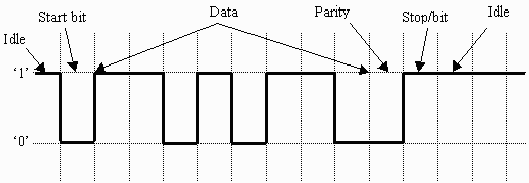
The two lines meant to transmit data use the same method to send a character. When a serial line is idle, it transmits a constant logic '1'. When either the DCE or the DTE wants to transmit data, it begins by sending a single bit called a start bit which is a logic zero. It does this for a bit period of 1.
After the start bit, the transmitting device transmits the character one bit at a time starting with the least significant bit. After the serial transmission of the character is completed, an optional parity bit might be sent. Once the parity bit is sent, the transmitting device sends a stop bit which is a logic 1. If no characters need to be sent right after this one, the line is left at a logic '1' value indicating it is idle.
Aside from the BAUD rate, there are a few things that can be configured for this interface. First, the number of bits being used to represent the data can be either 7 or 8. As I said earlier, ASCII was defined only for 128 characters or 7 binary bits.
Second, the interface may require more than a single stop bit. One stop bit is the most common, but 1½ or 2 is also possible.
Third, if the parity bit is used, there are different types of parity it can represent. These types are:
The image below is a same of the serial stream to send the letter 'k' (ASCII = 6B16) with odd parity and 8 data bits.

There are a number of other calculations on serial stream performance other than BAUD rate.
                               # of data bits

Data bits per second (DBPS) = ----------------- * BAUD

                               # of frame bits
and
                                  BAUD rate

Characters per second (CPS) = -----------------

                               # of frame bits
Notes developed by David Tarnoff solely for use by students in his sections of CSCI 2150.