Getting Oriented: Axes, Directions, Locations, and Positioning
Learning NC programming is often an adventure in going from one place to another; good NC programming is simply an exercise in going from one place to another on purpose. But, of course, as the character Buckaroo Banzai says "No matter where you go, there you are." For fictional brain surgeons, jet car drivers, and rock and rollers, that's all well and good. However, for precision machining, a programmer will need to be a bit more accurate...typically to at least four decimal places for most CNC controllers. To achieve such accuracy, the programmer must have a known frame of reference in three dimensional (3D) space for every move. Therefore, with every program move the machine makes, it will be moving (a) along one or more axes (b) in some direction (c) to a particular destination, and (d) then do something (typically, going somewhere else).
Which Axis is Which?
N/C cutter motion can be made along any of three axes, all of which are mutually perpendicular, that is, they are at exact right angles to each other. These axes of motion are identified by the letters X, Y, and Z, the same as in the familiar Cartesian coordinate system. Direction of motion along these three axes--right and left, in and out, up and down--is designated by a plus or minus sign. Most N/C machines will assume motion in the positive (plus) direction unless you specify the negative direction by using a minus sign. The direction or condition assumed by a N/C machine--when no specific direction has be been given--is called the default condition.
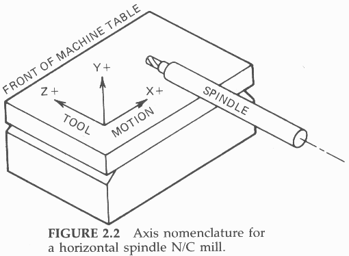
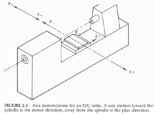
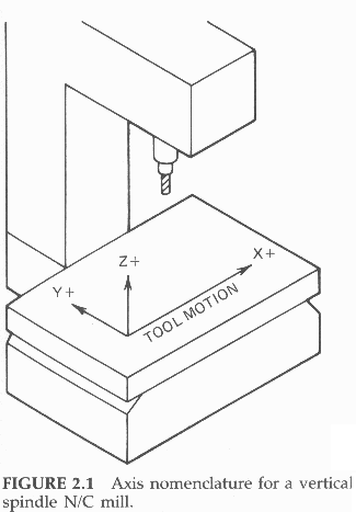 Z-Axis Which axis is which depends on the orientation of the spindle. The axis of motion that is parallel to the spindle axis is always the Z-axis. If the spindle is vertical (Figure 2.1), the Z-axis is vertical. Either the quill or the knee of a vertical spindle mill will move when a Z-axis command is executed. If the spindle is horizontal, the saddle or quill on a mill (Figure 2.2) or the carriage or turret on a lathe (Figure 2.3) will move parallel to the spindle axis when a Z-axis command is executed.
X-Axis The mill axis that moves right and left (as the operator is facing the front of the mill) is the X-axis for both vertical and horizontal spindle mills. For lathes, the X-axis is the cross slide (or turret) motion at a right angle to the spindle axis.
Y-Axis The Y-axis on mills is either the in-and-out motion--toward and away from the operator (vertical spindle) or up-and-down motion (horizontal spindle). Simple CNC lathes are two-axis machines and have no Y-axis.
It should be noted that complex, multi-spindle lathe-type machining centers or Swiss screw machines with multiple, automatic chucks equipped with so-called "live tooling" may have one of two Y-axes.

Which Direction is Which?
The positive cutter motion directions for a vertical spindle mill are to the right of the operator (X-axis), away from the operator (Y-axis), and up (Z-axis).
Horizontal spindle N/C mills are a little more confusing. For a sense of direction, one must be looking in the Z-minus direction, as if one's eye were stuck in the spindle and looking out at the workpiece. Then the positive cutting tool motion directions are to the right (X-axis), up (Y-axis), and toward the end of the spindle (Z-axis).
For an N/C lathe, the positive cutting tool motion directions are away from the headstock, usually to the right (Z-axis), and away from the spindle's axis (X-axis). For tool-in-the-rear machines, the X-plus direction is away from the operator. For tool-in-the-front machines, the X-plus direction is toward the operator.

Locating the Cutting Tool Point
The programmer doesn't have to tell the N/C controller where the cutter is. The controller always keeps track of the current cutting tool point location (the center of the cutter, at the tip) relative to a reference point called the origin.
The origin is that point from which all three axes emanate. Putting it another way, the origin is the location of the cutting tool point when all three axis counters are at zero value (X0, Y0, Z0). It is therefore the "zero point" from which either (1) all cutter coordinate location points are referenced (absolute positioning) or (2) the point from which the cutter starts (and ends) at the beginning (and end) of the program (incremental positioning).
The origin is usually a point whose location is designated by the programmer. Some older N/C machines have an origin with a preset fixed location within the machine's range of travel (usually on the surface of the table at its lower left-hand corner). For a lathe, the origin may preset at the spindle axis and the end of the spindle nose.
More commonly, it is wherever the axes--or more correctly, the cutting tool point--may be located when a certain button on the control panel is depressed, which "zeros" the axis counters in the controller.
A programmer assumes that at the beginning of a program the cutter is situated at some specific starting point on the workpiece, such as the upper left-hand corner or the center, with the end of the cutter "touching off" the top of the workpiece. All the N/C operator has to do when making a setup is to "jog" the cutter to that location and depress the "ZERO AXES" button to shift or "float" the origin to that location. This type is called a floating-zero N/C machine.

Absolute vs. Incremental Positioning
Some N/C controllers can accept only absolute positioning commands, while others can accept only incremental positioning commands. Newer CNC machine controllers can accept both absolute and incremental positioning commands. All the programmer has to do is tell the controller (by means of a code) whether the positioning commands are absolute or incremental. Thus the programmer can change back and forth from absolute to incremental positioning as often as desired by changing the code.
Absolute Positioning
Absolute positioning always tells the controller where to send the cutter relative to the
origin (rather than the current cutting tool point location). The controller always knows where the cutter currently is located, so it can calculate the distance and direction it must send the cutter to arrive at the desired destination.
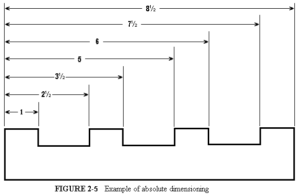
Figures 2.4 and 2.5 are drawings that illustrate the concepts of incremental and absolute dimensioning. These concepts of dimensioning are analogous to incremental and absolute positioning used in N/C.
Incremental Positioning
Incremental positioning always tells the controller where to send the cutter relative to the cutter's current location.
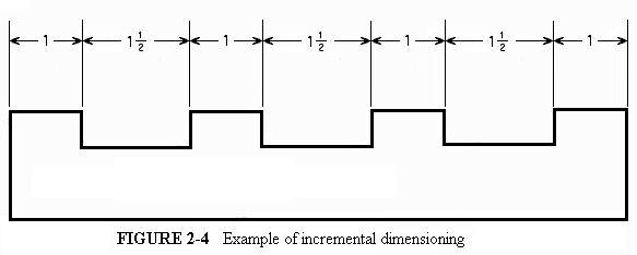
Thus, for incremental positioning, it is essential at the end of the program for the cutter to end up at exactly the same location from which it started out at the beginning of the program. Both the starting and end points must be identical.
This can be stated mathematically: The algebraic sum of all the axis moves in an incremental program must equal zero:

If the origin "shifts" with each successive workpiece, an error is introduced that becomes progressively larger with each successive workpiece. This is called a "progressive error."

Back to Contents Page
Updated Jan. 9, 2002
Copyright © 1988-2002 by George Stanton and
Bill Hemphill
All Rights Reserved
 Z-Axis Which axis is which depends on the orientation of the spindle. The axis of motion that is parallel to the spindle axis is always the Z-axis. If the spindle is vertical (Figure 2.1), the Z-axis is vertical. Either the quill or the knee of a vertical spindle mill will move when a Z-axis command is executed. If the spindle is horizontal, the saddle or quill on a mill (Figure 2.2) or the carriage or turret on a lathe (Figure 2.3) will move parallel to the spindle axis when a Z-axis command is executed.


