Although the set of notes you have requested is presented below, it has not been maintained since January, 2003. All of the information in these notes has been included in an on-line text titled Computer Organization and Design Fundamentals. The book is available in three formats, two of which are free electronic downloads. Please visit one of the following links in order to access the format you prefer.
Thank you for your interest in this textbook. Please feel free to e-mail me at tarnoff etsu.edu if you have any questions or comments.
-Dave Tarnoff
Last period, we covered the differences between a real-world analog signal and the digital signals used by computers. Now we need to examine some of the different forms of digital signals.
As with analog signals, digital signals change with time. Transitions from logic '0' to logic '1' and vice versa represent changes in data values or act as stimulus to make something happen.

Waveform of a positive-going pulse

Waveform of a negative-going pulse
Most digital signals, the ones carrying data or otherwise communicating in an asynchronous manner, have no pattern to their changes between values. These are called non-periodic pulse trains.
Waveform of a non-periodic pulse train
Some signals act as a heartbeat to a digital system. They, for example, might say, "Every 1/100th of a second, the system needs to do this." Another example of a periodic signal can be found as the output of a cyclical event such as the output to an engine's spark plug. A sample is shown in the figure below.
Waveform of a periodic pulse train
The defining characteristic of this type of waveform is that measuring between any two subsequent identical parts of the waveform results in the same value. This value is referred to as the period and it has units of seconds.

The period of a periodic waveform
There is a second method of measuring the periodic waveform and it is directly related to the period. This measurement is called frequency and it has units of cycles per seconds, also referred to as Hertz (Hz).
To convert the measurement of time for a period to the measurement of frequency in hertz, simply invert the period.
frequency in hertz = |
1 |
period in seconds |
If it takes 0.1 seconds for a periodic waveform to make a complete period, what is that waveform's frequency?
frequency in hertz = |
1 |
period in seconds |
|
frequency in hertz = |
1 |
0.1 seconds |
|
frequency in hertz = |
10 Hz |
If a waveform has a frequency of 10 kHz (10,000 Hz), what is the duration of its period?
frequency in hertz = |
1 |
period in seconds |
|
period in seconds = |
1 |
frequency in hertz |
|
period in seconds = |
1 |
10,000 Hz |
|
period in seconds = |
0.0001 seconds = 100 microseconds |
The last measurement of a periodic waveform is the duty cycle. The duty cycle represents the percentage of time that a periodic signal is a logic '1'. For example, the figure below, while it doesn't look very periodic, has a duty cycle of 100%, i.e., the signal is always a logic 1.

On the opposite end of the spectrum, a constant logic 0 is a logic 1 0% of the time and therefore has a duty cycle of 0%.

Somewhere in the middle is where most periodic signals fall. For example, if the digital signal is a logic 1 for 25% of the time and logic 0 otherwise, we get a signal with a 25% duty cycle.

The measurements for the period and the pulse duration are represented with T and th respectively as shown in the figure below.

In general, the formula for duty cycle is:
Duty Cycle = |
duration of logic 1 in seconds (th) |
x 100% |
period in seconds (T) |
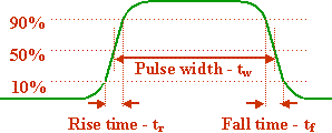
No signal is truly digital. A close examination of a digital signal reveals gradual transitions between logic 1 and logic 0 and vice versa.

The analog rise and fall of a digital signal
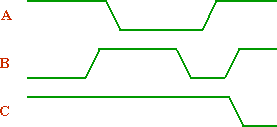
There are many ways to represent a digital signal over a period of time. The figure below represents a single line (a single switch with only two possible values, logic 1 and logic 0). The area between the horizontal hash marks on the rising and falling edges of the signal represent the period where the signal is undefined and in transition.

Representation of a single digital line
Sometimes, digital lines are grouped together to perform a single function. This circumstance may be represented with figures such as the one below.

Representation of multiple digital lines
Alternatively, these multiple lines can be combined into a more abstract representation such as the one below.

Alternative representation of multiple digital lines
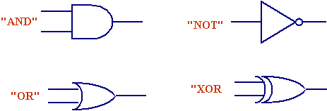
Below are the primary logic symbols used in digital design.

Basic logic symbols
Each of these symbols has one or more inputs (lines coming in from the left side) and one output (line exiting from the right). The symbols can be added together to create complex circuits. For example, adding a small circle to an input or an output of a logic symbol is identical to adding an inverter at that input or output.

Logic symbol with an inverter tied to the output
Logic 1's or logic 0's are sent into the inputs of these symbols, and by definition, a specific logic 1 or logic 0 is expected on the output. The following section describes which symbols have which outputs based on a certain set of inputs.
Now, we need a method to represent how to combine two or more binary signals to produce an output or function. In general, a truth table shows the relationship between columns of inputs and their associated outputs.
Inputs |
Outputs |
|
X |
X ··· X |
Y0 |
: |
: : |
: |
X |
X ··· X |
Yn |
For example, the "NOT" gate shown above has one input and one output. Therefore, there is one column of inputs and one column of outputs. For single input, there are exactly two possible states: logic 1 and logic 0. Therefore, there will be two rows of data for the NOT truth table. That table is shown below.

| Inputs | Outputs |
| A | Y |
| 0 | 1 |
| 1 | 0 |
The operation of the AND gate is such that its output is a logic 1 ONLY if both the inputs are logic 1. Otherwise the output is always a logic 0.

Operation of an AND gate
With two inputs and one output, the AND gate's truth table will have two columns for inputs and one column for outputs. It is shown below.
| Inputs | Outputs | |
| A | B | Y |
| 0 | 0 | 0 |
| 0 | 1 | 0 |
| 1 | 0 | 0 |
| 1 | 1 | 1 |
Note that if input A is a logic 0, it doesn't matter what input B is, the output is always 0. Similarly, if input B is 0, A's state does not matter. These situations are called "don't cares" and are represented by the symbol X. Using don't cares, we can redo the truth table for the AND gate.
| Inputs | Outputs | |
| A | B | Y |
| 0 | X | 0 |
| X | 0 | 0 |
| 1 | 1 | 1 |
The OR gate's output is set to logic 1 if either of the inputs are 1. It is 0 ONLY when both inputs are 0. Its truth table is shown below.
| Inputs | Outputs | |
| A | B | Y |
| 0 | 0 | 0 |
| 0 | 1 | 1 |
| 1 | 0 | 1 |
| 1 | 1 | 1 |
The XOR gate's output is set to logic 1 if the inputs are different and 0 when the inputs are the same. Its truth table is shown below.
| Inputs | Outputs | |
| A | B | Y |
| 0 | 0 | 0 |
| 0 | 1 | 1 |
| 1 | 0 | 1 |
| 1 | 1 | 0 |
If you have any confusion about binary, hexadecimal, or the conversion process between these numbering systems and decimal, you need to clear them up. If this set of note does not help, please see me during my office hours for further assistance.
When we count in a decimal integer manner, we start with the first digit, the one's place, and count until we reach the limit, 9. At that point, we increment the next digit, the ten's place, reset the first digit to zero, and start the cycle again.
Binary counting is performed the same way, the exception being that decimal has ten numerals (0 through 9) and binary has two numerals (0 and 1).
|
| ||||||||||||||||||||||||||||||||||||||||||||||||||||||||||||||||||||||||||||||||||||||||||||||||||||||||||||||||||||||||
Going from binary to decimal is quite straightforward. First, find the bit positions of all the bits containing a 1. Note that numbering the bit positions begins with the rightmost bit as number 0.
| Exponent/bit position (n) | 7 | 6 | 5 | 4 | 3 | 2 | 1 | 0 |
| 2 raised to the power of n | 128 | 64 | 32 | 16 | 8 | 4 | 2 | 1 |
Next, take the sum of 2 raised to the power of the bit-position for each position containing a 1. Since this last sentence could only have made less sense if it were written in Swahili, an example is shown below.
Example: Convert the binary value 110110100 to decimal.

Click here to see this same process done with a Flash 6 animation.
It is vital to remember when operating with a computer that only a finite number of bit positions will be available to store information. Therefore, it is important to know the maximum values that can be represented with a limited number of bits.
Maximum unsigned binary number represented with n bits = 2n - 1
Converting from decimal to binary is only slightly more complicated. As an example, we will convert the number 75.
Begin by finding the largest power of two that the number we are converting is greater than. Once you have done this, subtract that power of two from the original number and place a one in the bit position representing that power. In the case of 75, the largest power of two that 75 is greater than is 26 = 64. Therefore, we must place a one at bit position 6 and subtract 64 from 75.
| Exponent/bit position (n) | 7 | 6 | 5 | 4 | 3 | 2 | 1 | 0 |
| 2 raised to the power of n | 128 | 64 | 32 | 16 | 8 | 4 | 2 | 1 |
| Converted value | 1 |
Take the result of the subtraction, and repeat the above process. In the case of 75, 11 is the result of the subtraction. Therefore, 23 = 8 is the largest power of two that is still less than 11.
| Exponent/bit position (n) | 7 | 6 | 5 | 4 | 3 | 2 | 1 | 0 |
| 2 raised to the power of n | 128 | 64 | 32 | 16 | 8 | 4 | 2 | 1 |
| Converted value | 1 | 1 |
This cycle is repeated until the result of the subtraction is 0. Continuing with our example, the subtraction 11 – 8 results in a value of 3. 21 = 2 is the largest power of two still less than 3. Placing a 1 in bit position 1 gives us:
| Exponent/bit position (n) | 7 | 6 | 5 | 4 | 3 | 2 | 1 | 0 |
| 2 raised to the power of n | 128 | 64 | 32 | 16 | 8 | 4 | 2 | 1 |
| Converted value | 1 | 1 | 1 |
And lastly, 3 – 2 = 1 = 20, requiring us to place a 1 in the last bit position.
| Exponent/bit position (n) | 7 | 6 | 5 | 4 | 3 | 2 | 1 | 0 |
| 2 raised to the power of n | 128 | 64 | 32 | 16 | 8 | 4 | 2 | 1 |
| Converted value | 1 | 1 | 1 | 1 |
Filling all of the blank bit positions with 0 gives us the converted binary number, 01001011.
The binary numbering system is vitally important to computer engineering, especially at the hardware level. Binary numbers are used for:
As was indicated before, the number of each bit position of a binary value is equal to the exponent value represented by that position. Below are some terms that are also based on bit numbering/position:
Copyright 2001 by David L. Tarnoff. All rights reserved.