Computer Organization and Design Fundamentals by David Tarnoff is now available!Although the set of notes you have requested is presented below, it has not been maintained since January, 2003. All of the information in these notes has been included in an on-line text titled Computer Organization and Design Fundamentals. The book is available in three formats, two of which are free electronic downloads. Please visit one of the following links in order to access the format you prefer.
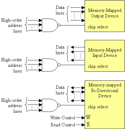
Thank you for your interest in this textbook. Please feel free to e-mail me at tarnoff etsu.edu if you have any questions or comments. -Dave Tarnoff Ports, Interrupts, and DMAReading: Digital Fundamentals sections 14-7 through 14-9 Memory MappingBefore Test 2, we discussed locating devices in an area of the memory map by using chip selects. The basic format had the address lines of least significance going to that address inputs of the chip and the address lines of higher significance going to drive the chip select. An active low ^R signal to indicate when data is being read from the memory and an active low ^W signal to indicate when data is being sent/written to the device. Data lines pass the actual data between the memory and the processor. 
Memory mapping is similar in that a chip select tells the device when it's being accessed and data lines pass data between the device and the processor. Memory mapped I/O, however, does not usually have address lines going directly to the chip, and only chips that can both input and output (bidirectional I/O) use both the ^R and ^W lines. 
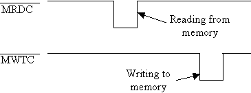
You may use as many address lines as you wish to isolate the chip select, just beware that EVERY address in the range defined for that chip select reads or writes to the same device. IMPORTANT: Intel doesn't use the ^R and ^W notation to label their read and write lines Instead, it uses the label ^MRDC for read and ^MWTC for write. 
Examples of hardware used to interface to portsBe sure to print out the first page only of the following data sheets:
Differences between I/O ports and memoryThe Intel processors have a "second bus" that operates in parallel with the memory interface. In fact, it uses the same address and data lines that make up the memory bus. There are slight differences, however, that make the operation of these two buses different for interfacing to I/O devices. I/O ports
Memory mapped I/O
Passing Data to/from PeripheralsThere are two ways to pass data back an forth between peripherals.
There are two types of interrupts
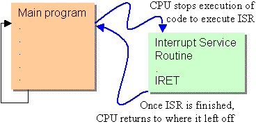
Why do we need interrupts? Well, the processor wouldn't want to constantly be checking the PC keyboard during a long computation. It would only slow things up. But if the keyboard could interrupt the processor only when a key press is available, then the processor could focus on more important things. Another use for interrupts could be for things like a network interface. If a network card has a buffer of data that is about to become full, it can interrupt the processor so that no data is lost to overflows. The format of an interrupt is a lot like that of a subroutines (or method or function if you wish). The difference is that the main program does not have to "call" them. They are called automatically by the CPU without affecting the main code. These "subroutines" are called Interrupt Service Routines (ISR). 
When the interrupt is called, the ISR can then pass data to and from the device just like communicating with memory. A programmable interrupt controller (PIC) maintains the interrupts by providing two things to the processor.
Direct Memory AccessUp to now, we have discussed memory-to-register transfers, register-to-register transfers, and register-to-memory transfers. Each of these methods involve passing data to or from the registers. If, however, we have to pass a piece of data between two portions of memory, the code would look something like this:
mov ax,[source address]
Two steps to move data from one place to another in memory. This is not a big problem for small amounts of data, but if we have a large block to transfer, the added transfer causes a significant delay. Direct Memory Access (DMA) bypasses the register by transferring data directly from one memory device to another. For example, to load a program from the hard drive to memory, DMA bypasses the processor and transfers the data directly. Figures 14-37 and 14-38 in your textbook represent this process quite well. Notes developed by David Tarnoff solely for use by students in his sections of CSCI 2150. |