Although the set of notes you have requested is presented below, it has not been maintained since January, 2003. All of the information in these notes has been included in an on-line text titled Computer Organization and Design Fundamentals. The book is available in three formats, two of which are free electronic downloads. Please visit one of the following links in order to access the format you prefer.
Thank you for your interest in this textbook. Please feel free to e-mail me at tarnoff etsu.edu if you have any questions or comments.
-Dave Tarnoff
Reading: Digital Fundamentals sections 14.1 through 14.3
Let's begin with some basic definitions to describe the internals of a microprocessor.
Bus -- A bus, as it pertains to a microprocessor is a bundle of wires that are grouped together to serve a single purpose. For example, in our discussion of memory interfacing, we talked about how the processor communicates with external memory devices through a group of wires. Some pass data, some pass address, and others act as control lines. These lines are "daisy-chained" from one device to the next. As an example, the image below shows A19 of the microprocessor connected to A19 of Memory Device 1 which is in turn connected to A19 of Memory Device 2. This is true for each of the address and data connections.

Register -- A register is a group of D flip-flops that have been grouped together for a single purpose. For example, I have been using the figure below to represent a grouping of 8-bits that would form an integer.

In a microprocessor, imagine each cell representing a flip-flop that would contain a single bit. An eight-bit integer might be temporarily held in one of these groupings. Two groups of flip-flops might contain two numbers to be added, the result then going into a third group of flip-flops. Each of these groupings of flip-flops would be referred to as registers.
Registers may contain:
Latch -- A latch is a register with a more specific different purpose. This grouping of D flip-flops is used to hold values to be output to other devices. For example, the is you wanted to control a number of LEDs say for a level meter, a latch would hold the appropriate 1's and 0's to drive those LEDs while the processor went off to do other things.
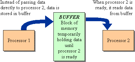
Buffer -- Rarely does a microprocessor operate alone in a device such as a PC. There will be multiple processors in addition to the main processor such as processors to control the video output, processors to control communication interfaces (USB, Firewire, Ethernet, etc.), or processors to maintain the DRAM. These processors are operating independently, and therefore may finish a process well before another processor is ready to receive the results. Multiple processors may also communicate from PC to PC as in a network.
If one processor is faster than another or if one processor is dedicated to a process that does not allow it to access data being sent from a second process, there needs to be a mechanism in place so that data is not lost. This mechanism takes the form of a block of memory that can hold data until it is ready to be picked up.

I/O ports -- I/O port (which is short for input/output port) is a general term referring to any connections that can be made between the processor and the outside world. A printer, for example, would be an I/O port. The computer can issue commands and send data to be printed and the printer can return its status. That same port can be used for a scanner or a Zip Drive allowing large amounts of data to be input to the machine.
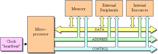
Below is the generic block diagram of a microprocessor system. It consists of the bus that we introduced during the discussion on memory interfacing. This bus includes the data that can be passed bidirectionally between the microprocessor and its external resources such as memory, address lines that define the chip and the memory location within the chip of the external resources, and the control lines orchestrating the transfers.

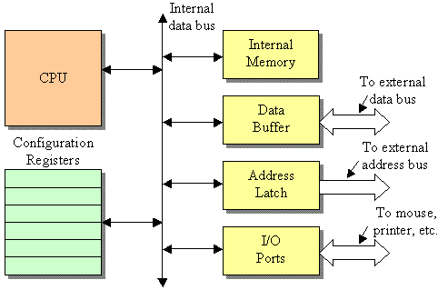
The internals of the microprocessor are essentially a microcosm of the microprocessor system shown above. As shown in the figure below, it too has an data bus that passes data between the CPU, the internal memory, the data buffer, the address latch, I/O ports, and the configuration registers. The difference is that this bus is contained entirely within the processor.

Internal memory is small, but extremely quick memory. It's used for any internal computations that need to be done fast without the added overhead of writing to external memory.
Data buffer allows for data to be passed to the external data bus which then goes onto devices such as memory. The data buffer takes care of data direction (is the data coming in or going out) and also provides signal conditioning for the world outside the chip.
Address latch maintains the address for use by the external devices such as memory.
I/O ports are specialized ports used by the processor. It differs from memory in that the port has a port number or identification that is used rather than having to use a memory address and pass data back and forth across the bus.
The configuration registers maintains the current configuration of the microprocessor. For example, if the microprocessor has a serial port (COM port), configuration data might include baud rate, buffer status, idle status, etc.
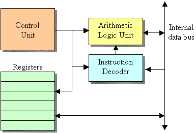
The CPU is then a microcosm of the microprocessor block diagram. It is the brains of the microprocessor.

Microprocessor chip designers create a basic set of instructions for every processor they design. These are really simplistic instructions that take baby steps as compared with high-level languages such as C++ or BASIC. Each instruction is numbered so that the instruction decoder can decipher them in order to energize the proper circuits to execute the function using the registers of the processor. These numbers are referred to as machine code. Machine code is the instruction set that machines understand.
Humans, however, understand words, so each machine code is given an "English" equivalent. These instructions in text form are called assembly language. There is a one-to-one correlation between assembly language instructions and the machine code. This brief set of definitions doesn't really bring across the point of how processors execute code. For that, let's make up a fake processor and create some simple code for it.
This processor only has two registers (remember, these are groups of D flip-flops), and they are named A and B.
| Register A | Register B |
To begin with, let's just brainstorm a list of possible operations we could perform on these two registers. Of course if you do this exercise on your own, you will come up with a different lists of operations, but below is a possible list.
This is great, except that the microprocessor does not understand English. It understands binary values that are to be interpreted by the Instruction Decoder shown in the CPU block diagram from earlier in these notes.
So let's give each command a number. Note that the numbers below are given in hex.
| Machine code |
Instruction description |
| 01 | Move data from A to B |
| 02 | Move data from A to memory |
| 03 | Move data from memory to A |
| 04 | Move data from B to A |
| 05 | Move data from B to memory |
| 06 | Move data from memory to B |
| 07 | Add A and B and put result in A |
| 08 | Add A and B and put result in B |
| 09 | Take the 2's complement of A |
| 0A | Take the 2's complement of B |
| 0B | Clear A |
| 0C | Clear B |
Next, let's create a program to move data from memory address 5E0016 into register A, then from memory address 5E0116 into register B, add the two registers putting the result into register A, and store the result into memory address 5E0216. The code looks like this with the text after the semi-colon representing comments. (i.e., they are ignored for program execution.)
	03    5E00    ; Move data from address 5E0016 into A

	06    5E01    ; Move data from address 5E0116 into A

	07            ; Add A and B and put result in A

	02    5E02    ; Move data from A to address 5E0216
In order for the computer to execute this code, it is stored in memory as a sequence of binary numbers. (No comments are stored with code.) Therefore, this program would look like the following in memory. (Numbers are represented in hex, but would be stored in binary.)
03 5E 00 06 5E 01 07 02 5E 02
Unfortunately, human beings are not very adept at programming with numbers. We prefer words that follow our linguistic nature. So for each of our commands, we made up a short word to represent the function of the machine code. This group of words is called assembly language.
| Assembly language |
Machine code |
Instruction description |
| MOVAB | 01 | Move data from A to B |
| MOVAM | 02 | Move data from A to memory |
| MOVMA | 03 | Move data from memory to A |
| MOVBA | 04 | Move data from B to A |
| MOVBM | 05 | Move data from B to memory |
| MOVMB | 06 | Move data from memory to B |
| ADDAB | 07 | Add A and B and put result in A |
| ADDBA | 08 | Add A and B and put result in B |
| CMPLA | 09 | Take the 2's complement of A |
| CMPLB | 0A | Take the 2's complement of B |
| CLRA | 0B | Clear A |
| CLRB | 0C | Clear B |
This allowed us to convert our machine code program into an assembly language program that made a little more sense to us when we looked at it. (It's still rather cryptic though.)
	MOVMA    5E00    ; Move data from address 5E0016 into A

	MOVBA    5E01    ; Move data from address 5E0116 into A

	ADDAB            ; Add A and B and put result in A

	MOVAM    5E02    ; Move data from A to address 5E0216
A program called an assembler takes this assembly language program and converts it to the machine code that the computer will be executing.
You, however, may be familiar with programming in a high-level language as C++ or VisualBasic. These programs are also broken down to machine code. It just takes an additional step. A compiler or interpreter is used to break the complex instructions into the "baby steps" of machine code. For example the C instruction if(B * C > 10) routine(); has multiple steps in machine code.
Once the compiler or interpreter breaks the complex instructions into the machine code, the computer can execute the program.
Every processor has an assembly language associated with it. Since the processors have different architectures, functions, and capabilities, the languages are usually quite different. There are, however, similarities.
There are three categories of instructions:
When we start programming in Intel 8088 assembly language, you will see these instructions and watch how they work.
The tiny, almost primitive instructions of assembly language cause some problems for programmers. The result is code that is:
There are, however, some benefits to programming in assembly language. Mainly, they are due to the fact that the programmer is working much closer to the electronics of the processor and is not separated by the compiler or O/S-dependent development environment. Programming in assembly language gives the programmer:
We will be programming in assembly language in the lab for the next two laboratory experiments, so it would be helpful for you to be introduced to the 8086 assembly language.
Like most programming languages, assembly language source code must follow a well-defined syntax and structure. The following is a description of the fields of an assembly language file.
Label Field -- A label is used to associate the memory address of a specific line of code or a memory location with a text string. (Remember, those humans like to see words, not numbers.) There are some rules it must follow:
Instruction or Opcode Field -- The instruction field contains the assembly language commands that the processor is supposed to follow to run a program. The command field must follow these rules:
Operand field -- The operand field contains the data that the assembly language instructions use to run. This includes addresses, constants, register names, etc. There is a link to a site later in this page that describes some of the guidelines operands must follow.
Comment Field -- Last of all, we have the comment field. The ways to represent comments in assembly language differ from assembler to assembler. For most assemblers, comments begin after opcode/operand with a semi-colon. The assembler ignores everything followed by the comment character until a carriage return/line feed (CR/LF).
Assembly language can be very difficult to read. It is for this reason that comments are critical to the source code documentation of an assembly file.
Notes developed by David Tarnoff solely for use by students in his sections of CSCI 2150.