Using the verbal description per State Flag website as a guide:
- Create a scale drawing of athe Tennessee state flag that
- is horizontally hung (i.e.; with the white and blue bands to the right, and
- has the width of the blue stripe equal to 0.250 inches.
(See directions below for color/hatching specifications)
- Save your work as "ASSIGN27.DWG" in your personal directory space.
- Insert, position, and scale the BORDER.DWG file into the drawing. Explode and edit the individual
elements as required, specifically the Dwg Name, Date, and Dwg No.
Again, make sure your name is in the Dwn By space.
- When you are finished creating the required geometry and revising the title block, save your work.
Backup drawing using desired removal media.
|
 |

To color in the red body, blue bar, and white stars and thin bar, you can do it one of two ways:
- Vector Fill:
- Use the AutoCAD line draw and either the "join" &/or "pedit" (polyline edit) commands to generate new, closed (i.e. water tight) boundries.
It is strongly suggested that you use multiple layers for the boundry geometry and and hatch/solid fills.
- From the main AutoCAD menu, open the Draw->Hatch dialog box.

- Once the "Boundary Hatch and Fill" dialog box opens, in the "Hatch" tab,
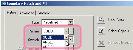
open the "Pattern" item by clicking on the right hand, down arrow.
Move the cursor to the scroll bar on the right hand side and scroll up (see below).
Click on the word "SOLID" to choose a solid color fill.

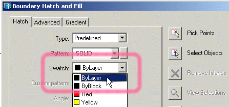
- Directly below "Pattern", open the "Swatch" choices and either
set a color or set to "ByLayer" as desired (see below).

- Click on the
 button. The "Boundary Hatch and Fill"
dialog box will then disappear. Select one or more closed shapes and press the button. The "Boundary Hatch and Fill"
dialog box will then disappear. Select one or more closed shapes and press the
![[Enter]](images/enter.gif) key on the
keyboard to return to the "Boundary Hatch and Fill" dialog box. key on the
keyboard to return to the "Boundary Hatch and Fill" dialog box.
- Press the
 button.
If the solid fill does not appear, you will probably need to redit the
polyline boundary(s); troubleshoot and make revisions as required. button.
If the solid fill does not appear, you will probably need to redit the
polyline boundary(s); troubleshoot and make revisions as required.
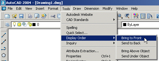
- Use the Tools->Display Order command as required to move the fills forward or
backward in the drawing order.

- When all desired fills have been completed, resize the final image as desired and capture it
using the raster capture method outlined below.

- Raster (bitmap) capture:
- Use the AutoCAD realtime zoom function to appropriately size the flag;
- Capture the image using the
 (Print Screen) keyboard key;
- Paste the screen shot image into a raster-based image editing program
(e.g., Windows Paint,
Adobe
Photoshop,
LView Pro, etc.)
- Crop, fill boundries, edit, and save image as desired.
|


