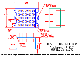
- Create the geometry per the drawing. Note the following:
- Notice the smmetrical nature of the object. To locate the test tube holes easily,
you can make the center hole the absolute X,Y zero. Later, you can shift the
origin to the lower left hand corner of the botom view (You will be making a
3D model of this part later in the term).
- The thickness of the part is 0.063," a standard thickness
for sheet metal. This thickness plays a role in the radii of the bends in the top view.
- Note that the hole-to-hole distances are noted as "equally spaced." You will need to
determine the exact locations and spacing of the twenty-five (25) through holes in the top.
(Hint#1: They are "equally spaced;" use the "divide" command appropriately).
(Hint#2: Notice the "minimum edge distance" note at the bottom of the drawing).
- Dimension the drawing using appropriate sized text.
- Save your work as "ASSIGN28.DWG" in your personal directory space.
- Insert, position, and scale the BORDER.DWG file into the drawing. Explode and
edit the individual elements as required, specifically the Dwg Name, Date, and
Dwg No. Again, make sure your name is in the Dwn By space.
- When you are finished creating the required geometry and revising the title block,
save your work and make backup(s) on some sort of removable or cloud-based media
(e.g., a USB disk &/or E-mail). Submit his assignment electronically to your instructor as directed.
- If directed, install one of the Wilson-Wallis HP Plotter drivers
and then plot the file in landscape mode on B size paper (11x17). Turn in the plot to your instructor.
|


