If the goal of a commercial manufacturing operation is to make money, making only high quality parts in a cost-effective manner should be the goal of the CNC programmer. A good rule of thumb for CNC programmers to follow is to assume that a minimum production run of 1000 parts will be made by competent and literate operators who are otherwise completely ignorant of the new part and program operation.
The most important aspect of making parts on a CNC machine is, of course, having a program that does exactly what the programmer wants it to to make a perfect part. The achieve that goal, however, the workpiece must be securely located and held during all machining operations. A part's quality will depend a great deal upon the quality of the tooling used to make it. Whenever possible, the CADD designer and CNC programming team should engineer the part and tooling to be as robust as possible (with an eye towards achieving the optimum balance between cost and quality).
To accomplish this, the part and tooling should be:
When locating the workpiece, use mounted dowel pins, a finger stop, or a single dowel pin mounted in a toolholder.
Another of the most important aspects of successfully manufacturing quality parts is ensuring complete communication from the CNC programmer to the operator. Typically, students have the luxury of writing programs only for themselves and immediately testing/running their programs, Consequently, there is little consideration given to an important aspect of programming: maintenance. In production environments, however, often a programmer will be working off-line to develop a program or set of programs that will be run by an operator at some later time from another building or even another country. Also, programs will typically be revised a couple of times during the product lifecycle to correct mistakes or optimize processes.
It is therefore important that the CNC programmer develop a thorough set of instructions including information concerning the part, filename, drawing(s), revision history, setup instructions, and operating instructions. As a typical EIA-274 controller "reads" only the CNC program information physically located between the two '%' characters, it is convienent to use the space above the first '%' character as a program header.
A sample program header is shown below:
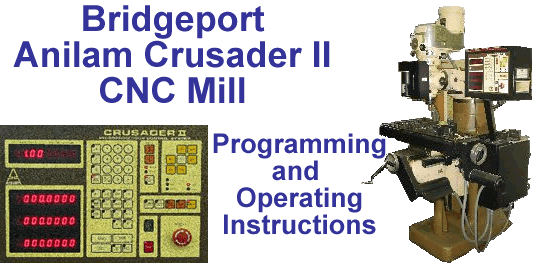
Part:			Wheel, Trolley - Modified 64mm-88A RollerBlade
Filename:		64mm-RB-mod.txt , Rev. A
Date:			Sept. 6, 2002
Programmer:		Bill Hemphill

Drawing No.:		RB-mod.dwg
Controller/Mill:	Anilam Crusader II / Bridgeport

Set-up Instr:		(this doc)
Tooling Reqd:		Quick Mount Plate for Trolley Wheels
Material:		64mm-88A Roller Blade MICRO wheel (Kit 80011012-UPC23044 01627)

Revision History
  	Dev		Sept. 2, 2002	Development
	Beta 1.00	Sept. 4, 2002	Begin Beta Testing
	Beta 1.01 	Sept. 5, 2002	Mod01 Boss Offset (no code change/reorigin Mill)
	Released	Sept. 5, 2002	Two good wheels shipped to client (prototypes)
	A		Sept. 6, 2002	Revised Feedrates/Added WCP/Dwell to Sub #22 end

						  FEED RATES		SPNDL
TOOL	DESCRIPTION			 RAD   PLUNGE   XVERSE	SPEED
-----	--------------			-----  -----    -----		-----
#6	1/2 Dia 2-flute End Mill	0.250	 020	   150		1,800
#8	5° Taper 3-flute End Mill	0.125	 020	   200		2,000

Setup Instr:	Locate ABS X,Y on Mod01 Boss (X=-2, Y=-3)
		TLOs:  Z = 0 at TOP of Q/M CARRIER PLATE

Tool Change Point		(TCP):	( -4.50 ,-4.50 )
Workpiece Change Point	(WCP):	(  0.00 , 5.25 )

			Loading Instructions and Tool Usage
----------------------------------------------------------------------------------------
Tool #   Process Description				     	Program Entry Point
----------------------------------------------------------------------------------------
 >>>> 	Install Quick Mount Base and Plate
 >>>> 	Set machine origin
 >>>> 	Set/Confirm ALL TLOs
 >>>> 	Install RollerBlade 64mm-88A MICRO wheel
	  flat side up and secure with Mod01 Holder
  6	Circular Pocket Mill for 60002Z Bearing			N0000
 >>>> 	Install RollerBlade 64mm-88A MICRO wheel
	  flat side down on Mod02 Boss.
 >>>>	Secure with bushing and 3/8-16-UNC Allen screw
  6	Mill outer section of outside face				N0110
  8	Mill circumference at 5° taper 				N0120
 >>>> 	Remove Allen head screw and bushing.
	  Mount Mod03 Holder & secure.
  6	Mill inner section of outside face				N0140
-------------------------------------------------------------------------------------------
![]()
![]()
![]()
Copyright © 2003 George C. Stanton & Bill Hemphill
All Rights Reserved
Last updated on Feb. 15, 2003 by Bill Hemphill