- To get started, either download the Anilam program template
or reuse your CNC code written for Lab #1. Edit the content of the (new) file to reflect the specifics
of this program assignment and (pen plot) set-up. The file's tab spacing is set at 10.
Appropriately rename the file to the DOS 8.3 filename format when saving
(e.g., zwkh23-2.cnc.
- For detailed G-code program syntax information, use the on-line
Anilam Crusader II CNC Mill
Programming & Operating Instructions Manual.
- Use the lab's CNC file server to upload the program to the Anilam controller.
- Download, install, and learn to use ETSU's DOS-based EIA-274 comment stripping utility:
- Use the '$' sign as a comment delimitator. Writing the program first in comment form
(i.e., psuedo-code) will often prevent many programming errors.
- Use the '{' and '}' ignore block character pairs as a block delimitators to break
the program into pieces during testing. Debugging goes faster if the whole program
doesn't have to run each time.
- To save time during program development and debugging, use the same TLO data for
all three pens. After the tool paths have been proven, set the TLOs to their correct lengths.
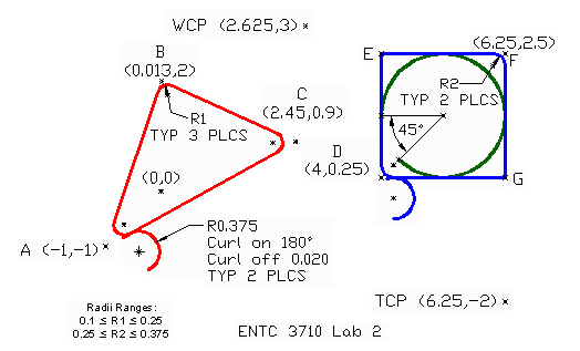
- As the problem geometry data has already been specified for this assignment (TCP, WCP,
shape start points, etc.) , it is quite easy to develop the CNC tool path data using absolute
(ABS) points. Looking ahead to
Lab #3, you might want to consider programming parts of the
assignment using incremental (INCR) values (e.g., the triangle, the square, and the arc
shapes). Granted, programming in incremental units is a bit more time consuming (and
for this assignment, unnecessary), but the time spent now will save time later when
revising the code to called subroutines and loops (which are typically programmed in
incremental values to ensure "portability").
|


