Feedback: Open vs. Closed Loops
The controller needs to know the progress of the cutter in its journey to its destination in order to control the cutter's path and velocity. Two methods are utilized to achieve this.
Open Loop Systems
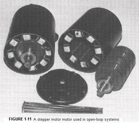 The first method is called an open-loop system. It uses a special kind of motor called a stepper motor (Figure 1.11) to drive each axis. A stepping motor has no brushes, commutator, or slip rings. It has a stator into which internal grooves have been cut. The stator is wound with several coils of wire through which a direct current is fed. By controlling the magnitude and direction of the current in each of the various coils, the location of the stator's magnetic field poles can be manipulated and controlled. The rotor consists of a very strong permanent magnet into which grooves have been cut, each groove creating a magnetic pole. There are a few more grooves in the permanent magnet rotor than there are in the electromagnetic stator. This sets up a vernier relationship between the stator poles and the rotor poles, permitting rotation in discrete increments (or steps) of 1/200 of a revolution, which a DC servo motor cannot do.
The leadscrew has five threads per inch; hence five revolutions of the leadscrew will advance it exactly one inch and one revolution will advance it 1/5 (0.200) inch. Since the stepping motor's rotation can be divided into 200 parts, 1/200 of a revolution will advance a leadscrew connected to the stepping motor exactly 0.001 inch. Likewise, 2/200 of a revolution will advance the leadscrew 0.002 inch; 47/200 revolution = 0.047 inch; 2,789/200 revolution = 2.789 inch, etc.
The feedrate is controlled by how rapidly the stator's magnetic field--and hence the rotor--is rotated. Five rotor revolutions per minute yield a feedrate of one inch per minute (IPM). Fifty rotor revolutions per minute = 10 IPM, etc.
The controller simply keeps track of the revolutions of the stator's magnetic field to determine where the cutter is. It is assumed the poles of the motor's rotor keeps pace with the stator's rotating magnetic field. There is no provision for detecting if the stepping motor's rotor "skips a pole," resulting in an error (it rarely occurs). No information is fed back to the controller that would permit the controller to correct position errors. Since there is no "looping back" of position information, such a system is said to be an "open-loop" system.
Open-loop systems are popular on smaller N/C machines. They are less complex, less costly, and less expensive to maintain. However, an open loop system's resolution (0.001 inch) is often coarser than the resolution on many closed-loop systems (sometimes as fine as 0.0001 inch) and an open-loop system can't detect whether an error in positioning has occurred.
Closed-Loop Systems
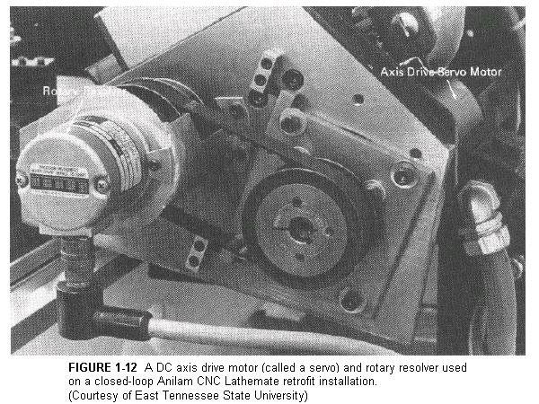
A closed-loop system uses conventional variable-speed DC motors, called servos, to drive the axes. A DC motor is the highest torque electric motor available. It is instantly reversible. However, it cannot be made to turn an exact fraction of a revolution like the stepping motor. It can only be turned on and off, speeded up or slowed down, run forward or run reverse. In order to keep track of axis position, a servo must be fitted with a position-sensing device called a resolver.
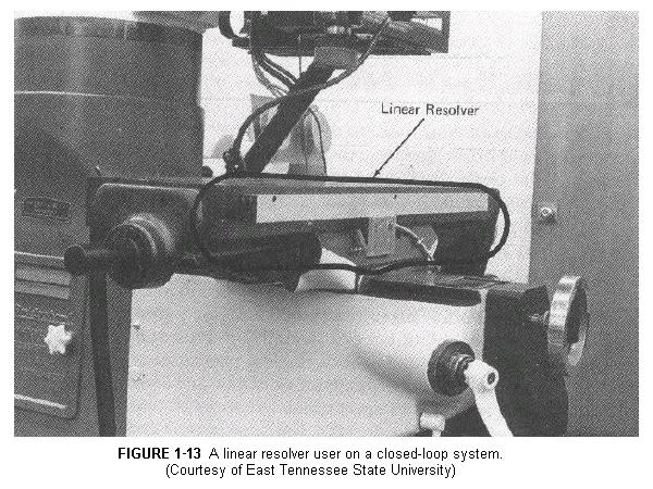
There are two types of resolvers in common use. One type is a rotary resolver (Figure 1.12). Its purpose is to measure angular or rotary motion. It is coupled to an axis drive motor or leadscrew and generates an electronic signal according to how far the the resolver's rotor (and hence the leadscrew) has rotated. The second type of resolver is the linear resolver (Figure 1.13). It is connected directly to the axis slides, not the leadscrews. It measures linear motion directly and is unaffected by wear or clearance between the leadscrew and its nut or by worn leadscrew bearings. The controller keeps track of the number of complete revolutions the resolver has turned and analyzes the resolver's electronic signal to determine fractional parts of a revolution.
The resolvers "feed back" a signal to the controller. The controller analyzes that signal to determine where the cutter is and compares that information to where the cutter should be. The controller then knows which direction to run the axis drive motors and when to shut them off so they stop at exactly the correct location. Although it rarely needs to, it can also make the motor reverse and back up if it overshoots its destination. Since an electronic signal is "looped" or fed back to the controller, such a system is said to be a "closed-loop" system.
Because DC servomotors can be instantly reversed and have higher torque, permitting them to handle heavier loads than can stepping motors, they are used in closed-loop systems for the larger N/C machines as well as for many of the smaller N/C machines. Since closed-loop systems can detect and correct positioning errors, some are capable of positioning accuracy as fine as 0.0001 inch. However, closed-loop systems are more complex than open-loop systems; hence they are more costly and more difficult to maintain.

Back to Contents Page
Updated Jan. 9, 2002
Copyright © 1988-2002 by George Stanton and
Bill Hemphill
All Rights Reserved