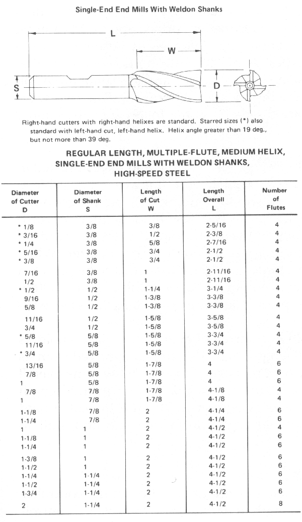
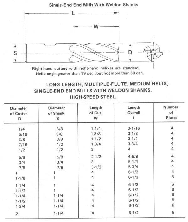
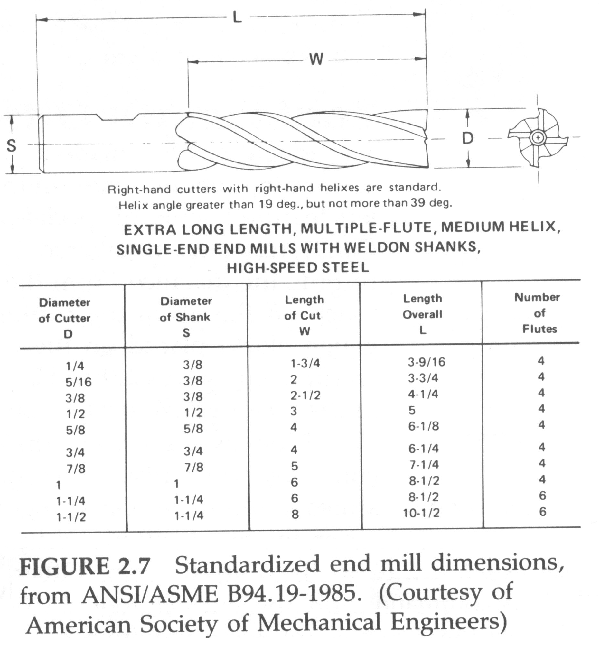
High-speed steel end mills are available for each diameter manufactured in three standard lengths: regular, long, and extra long. Figures 2.7(a)-(c) show the lengths of the cutting edges and shank for cutters of various diameters for each type of length.
Z-axis cutting tool motion commands control the location of the end (or tip) of the cutter. Many, if not most, N/C programs require the use of more than one cutter. Roughing operations are best performed with a two-flute cutter, because it is less prone to becoming clogged (its deeper gullets have more room for chips) and it can plunge cut. Finishing operations are best performed with four-flute cutters, because they are more rigid (less deflection) and have more cutting edges (better surface finish). Machining holes often requires drilling in several steps followed by boring (to "true-up" the location) and reaming (for diameter control). The odds are that none of the cutters will be the same length. If they are not, some provision must be made to compensate for their length differences. The two ways that this can be accomplished are discussed in the following subsections.
![]()
The earlier, pre-CNC, N/C machines used cutters that had to be adjusted in their toolholders to a predetermined overall length. If it was not possible to set all of the cutter/toolholder lengths to the same value, the programmer had to know the difference in length of each toolholder/cutter. Accordingly, the programmer had to "offset" the appropriate Z-axis commands in the program to account for the difference in length of each cutter. When making the setup on the N/C machine, all of the cutters had to be preset in their toolholders to the exact overall length called for in the program. Often the programmer had to actually preset the cutting tool lengths before writing the program.
It is no simple task to position an array of cutters in their toolholders so each is exactly a given overall length. When a cutter is removed from its toolholder for sharpening, it must be reinstalled to exactly the same overall length, which requires a special fixture (Figure 2.8). The overall length decreases when a toolholder's collet is tightened, because the collet (and cutter) are drawn into the toolholder, requiring patience and skill to achieve accurate settings.
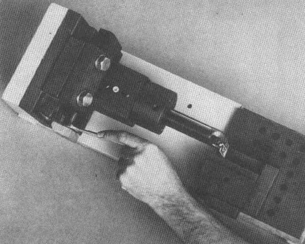
FIGURE 2.8 Fixture used for presetting cutters in their toolholders to a predetermined length
(Courtesy of Cincinnati Milacron)
![]()
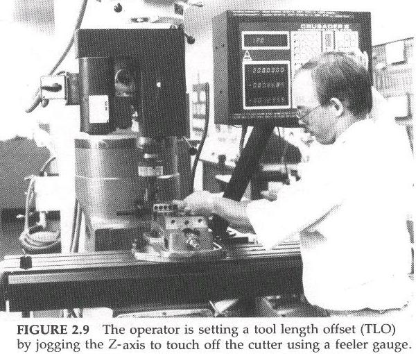
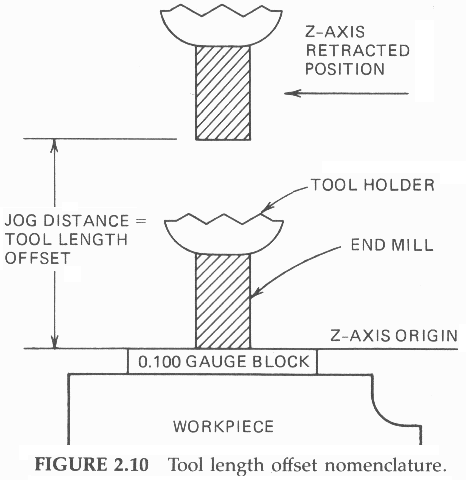
The advent of CNC made it possible to store information in the controller concerning the difference in the length of each cutting tools. CNC controllers feature a series of special-purpose memories called Tool Length Offset (TLO) registers, numbered 1 through 24--or more. Each TLO register records the distance (from the fully retracted position) required to jog, or touch off the tip of the cutting tool on a feeler gauge (e.g. a 0.100-inch gauge block) placed on the Z-axis origin plane, typically the top of the workpiece (Figures 2.9 and 2.10). (Most programmers will consider the top of the feeler gauge itself to be the Z-axis origin.)
Whenever the program calls for cutting tool no. 1 to be used, the controller will access TLO register no. 1 and "plug in" the jog distance it stores to offset the Z-axis register the amount required to be at zero value when the tip of cutter is at the Z-axis origin. Some controllers will actually send the cutting tool tip (via rapid travel) to the Z-axis origin. Other controllers simply offset the Z-axis counter and require a Z-axis command to position the tool tip at the Z-axis origin. Setting the TLO registers works as follows.
Subsequent removal of a cutting tool for resharpening or replacement requires only resetting the TLO for that particular tool. All other TLOs remain intact.
The CNC programmer can write the program knowing the Z-axis origin will be the same for all cutting tools (irrespective of their length), at the top of the feeler gauge. Of course, the programmer must specify to the N/C operator or set-up personnel what thickness of feeler gauge to use and where to place it when setting the TLO registers.
![]()
| Next: Subroutines and Loops |
|---|
Back to Contents Page
Updated Jan. 9, 2002
Copyright © 1988-2002 by George Stanton and
Bill Hemphill
All Rights Reserved