Typically, each line is a CNC program directs the movement of the cutter. All N/C programs must "tell the cutter" (1) where to go; (2) how to get there; (3) how fast to get there, and (4) what to do when it arrives.
The first essential element of N/C programming is to tell the controller where to send the cutter (its destination). This positioning information will be specified either incrementally (from the cutter's last position) or absolutely (from the origin). Such information will consist of one or more positioning and coordinate values:
e.g., G70 G90 X0.045 Y-3.980
the cutter will move to a point 0.045 inches along the X axis and -3.980 inches along the Y axis.
The second essential element of N/C programming is to tell the controller how the cutter is to get there (i.e. the path to follow). Commands are given that will cause the cutter to move along one, two, or three axes. In order to machine surfaces that are not parallel to one of the N/C machine's axes, the motion of two or more axes must be "timed" or coordinated to with other. This capability is called linear interpolation. Not all older N/C machines have this capability.
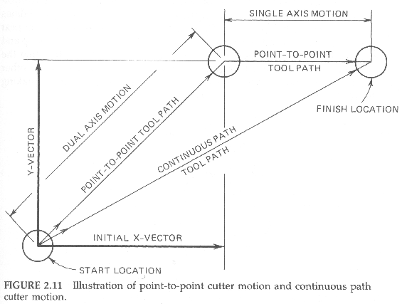
Many N/C machines make two-axis moves by moving both axes simultaneously, at the same velocity, which results in a 45 degree angular cutter path (Figure 2.11). Only cutter destinations with equal axis vectors (for example, identical X- and Y-axis values) will be situated along this path. Destinations with unequal vectors (either the X-axis or Y-axis value is larger) will not be situated along this path. Such destinations are reached by moving both axes simultaneously until the shorter vector has been completed and then continuing along the longer axis until the destination is reached. Such a cutter path is said to be "doglegged." N/C machines that operate only in that manner are called point-to-point machines. They are usually intended for drilling and boring operations rather than milling, although some are capable of performing nonangular milling cuts if the feedrate can be controlled.

Besides the linear movement, CNC equipment is capable of circular interpolation, the coordination of axis motion to yield an arc path. By dividing the desired arc into a series of tiny, connected, linear movements; the controller can move the cutter along a complete or partial circular path. Obviously, in circular interpolation movements, the programmer must decide wheither to follow a clockwise (CW) path [ G03 ] or counter-clockwise (CCW) [ G04 ]. Additionally, in circular interpolation, the arc center must be specified. As the X, Y, & Z axis lables are already used, the EIA 274 format uses the I, J, & K words to specify arc center coordinates. In the following example,
| G91 |
| G03 X0.0453 Y-3.9802 I-0.1802 J0.3655 |
relative to it's last destination (G91), the cutter will move in a clockwise direction to a point 0.0453 inches along the X axis and -3.9802 inches along the Y axis in an arc with a center located (again from the point of it's last destination) at -0.1802 inches in the X axis and 0.3655 inches in the Y axis. (Yes, it is getting complicated, but circular interpolation will be explained in detail in Chapter 3.)
Linear and circular interpolation are found on N/C machines that are said to be of the continuous path type. Such N/C machine controllers are capable of coordinating the simultaneous motion of two or more axes. This permits the cutter to arrive at its destination along each axis at exactly the same instant, no matter how long each of the axis vectors involved in the move may be. This capability permits the machine to make angular cuts at any desired slope.
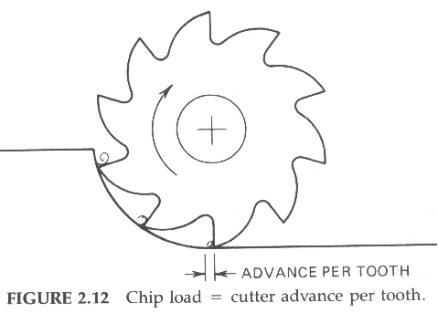
 The numerical value of IPM or MMPM feedrate is the product of three factors: (1) the spindle speed in revolutions per minute (RPM); (2) the number of teeth on the cutter; and (3) the chip load (how far each tooth of the cutter is to advance into the workpiece parallel to the direction of travel--see Figure 2.12). Simply multiply these three factors together and the answer is the feedrate.
Last, but not least, the fourth essential element of N/C programming is to tell the controller what to do when the cutter reaches its destination. Many possibilities exist: it could be told to send the cutter somewhere else--to its next destination; (2) it could be told to drill a hole; (3) it could be told to stop and wait while a clamp was being repositioned; or (4) it could be told that the program is finished and to return the cutter to the origin or some other "home" point and to rewind the tape or memory in preparation for making the next part.
Other commands may or may not be used depending on the capabilities of the controller and the requirements for machining the particular workpiece. Such commands may start and stop the spindle and determine the direction of rotation, set the spindle speed, turn the coolant on and off--either as a spray mist or a flood, tighten or disengage hydraulic clamps, or operate other auxiliary equipment. But all N/C programs must "tell the cutter" (1) where to go; (2) how to get there; (3) how fast to get there, and (4) what to do when it arrives there.
| Next: Review Questions for Chapter 2 |
|---|
Back to Contents Page
Updated Jan. 9, 2002
Copyright © 1988-2002 by George Stanton and
Bill Hemphill
All Rights Reserved