Spindle speed selection involves two items: (1) knowing what speed is correct for a given situation, and (2) knowing how to specify that speed in an N/C program. Some N/C machines feature programmable spindle speed selection; other N/C machines require the spindle speeds to be manually set and manually changed.
Programmable spindle speed capability requires an N/C machine to have a variable-speed motor, usually a DC motor with an electronic tachometer to feed back spindle RPM information to the controller. This complexity is usually restricted to the higher priced N/C machines, such as machining centers and turning centers.
Smaller N/C machines usually have single-speed AC induction motors. Speed changing is manually achieved by changing V-belt pulley positions, shifting a gearbox, or shifting a variable-speed pulley drive.
The format for encoding the spindle speed depends upon the N/C machine being programmed. If the spindle speed format for a particular machine is S40, the address word S is followed by four digits to the left and zero digits to the right of a decimal point. Thus a spindle speed of 3200 RPM would be encoded S3200; 320 RPM = S0320; 32 RPM = S0032.
Whether the spindle speed selection is encoded into the program or manually set by the N/C operator, the N/C programmer must determine what the spindle speed should be. The speed is then either encoded into the program or specified to the N/C operator, to be adjusted at appropriate points in the program, usually in conjunction with cutting tool changes.
![]()
The correct spindle speed is determined by many variables that can interact and become very complex. Some of the variables defy measurement, so we'll reduce these to only three parameters for "normal" conditions (whatever "normal" means).
The first two of these parameters relate to the the number one enemy of cutting tool life: HEAT. The first parameter that determines the amount of heat generated is the relative velocity between the cutting edge and the workpiece. The velocity in turn is a function of the cutter or workpiece diameter, whichever rotates. For a given RPM, the larger the diameter, the higher will be the velocity and the greater will be the heat generated.
The second parameter concerns the kind of material being cut, specifically its machineability. The more difficult a material is to machine, the more heat will be generated and the higher will be the temperature of the cutting tool. Rubbing friction also generates some heat, but it is relatively minor, unless the cutting edge is especially dull.
The third parameter concerns the the cutting tool's ability to resist heat--or more correctly, elevated temperature. The kinds of cutting tool materials commonly used, in the order of their ability to withstand elevated temperatures, are high-carbon steel, high-speed steel, cast alloys (such as Stellite), tungsten carbide, and ceramic oxide. Cutting tool materials seem to have a threshold temperature above which they quickly loose their ability to maintain a sharp cutting edge. Their approximate threshold temperatures are shown in Table 3.1
| Table 3.1 Cutting Edge Breakdown Threshold Temperatures for Various Cutting Tool Materials |
|
|---|---|
| Cutting Tool Material | Threshold Temp. (° F) |
| Plain High Carbon Steels | 300 |
| High Speed Steel (HSS) | 1100 |
| Cast Alloys | 1300 |
| Tungsten Carbide | 1600 |
| Titanium Carbide | 1600 |
| Ceramic Oxides | 2100 |
 In addition, the following factors can affect the RPMs.
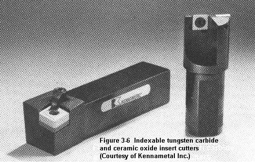
The generation of heat is no problem if the heat can be carried away as fast as it is generated, as by using a coolant. Likewise, elevated cutting tool temperatures are OK if the cutting tool material has an elevated threshold temperature, as with the carbide and ceramic cutting tools (Figure 3.6).
One must be cautious about cutting speeds that are sufficiently high as to overheat the workpiece, causing it to expand. Upon cooling, the workpiece will shrink and possibly be undersize. Furthermore, overheating can degrade the heat treatment of some workpiece alloys.
Table 3.2 shows cutting tool velocities (cutting speeds) that can be safely used for most "average" conditions with high-speed steel cutting tools. Consult manufacturer's data sheets for other cutting tool materials and cutting tools with special coatings, etc.
| Table 3.2 Cutting Speeds for Various Materials in Surface Feet per Minute* * These figures are approximate maxima; lower velocities are not detrimental to tool life, only to economics. |
||
| Workpiece Material | Cutting Tool Material | |
|---|---|---|
| High-Speed Steel | Tungsten Carbide | |
| Superalloys | 10 to 25 | 30 to 75 |
| Tool steels | 25 to 75 | 75 to 200 |
| Stainless steels | 25 to 75 | 75 to 200 |
| High-carbon steels | 25 to 75 | 75 to 200 |
| Alloy steels | 25 to 75 | 75 to 200 |
| Medium-carbon steels | 50 to 100 | 150 to 300 |
| Low Carbon Steels | 100 to 150 | 300 to 450 |
| Leaded mild steels | 200 to 400 | 500 to 1000 |
| Yellow brass | 300 to 750 | 1000 + |
| Aluminum | 500 to 1000 | 1000 + |
![]()
It is important to understand that there are a lot of variations in cutting tool materials and in workpiece materials. The results of the following equation may have to be revised upward or downward to suit the specific conditions of each machining situation. But the numbers should at least "be in the ball park."
| Spindle Speed (in Revolutions Per Minute or RPM) |
= | Cutting Tool Velocity (in surface Inches per Minute) ------------------------------------------------------ Circumference of Cutter or Workpiece (in Inches) |
Cutting tool velocity (cutting speed) is normally expressed in feet per minute rather than in inches per minute. The circumference of a cutter or workpiece is its diameter * pi (3.14159). (The "*" means multiply.) Thus the equation can be restated as:
| RPM | = | Cutting Tool Velocity (in SFPM) * 12 --------------------------------------- Diameter (in Inches) * 3.14159 |
| where SFPM stands for surface feet per minute. | ||
By rounding the value of pi down to 3 and "canceling" it into the 12, the 12 becomes 4 and the equation can be restated in a more simplified form and "burned" into one's brain, as all experienced programmers do
|
For example, a 1.500 inch diameter 2-flute HSS end mill cutting in half-hard yellow brass with a cutting tool velocity of 500 SFPM (Table 3.2) would require a spindle RPM of 500 * 4/1.5 = 2000/1.5 = 1333 RPM. This figure would need to be decreased if the depth of cut was deep and/or the feedrate was high. It could be increased for a light finish cut or if coolant was used.
![]()
Some N/C lathes are capable of being programmed to maintain a constant cutting velocity rather than a constant RPM. When facing, cutting contours and tapers, etc, the spindle speeds up as the cutter moves along the lathe's X-axis (cross slide) toward the spindle axis and slows down as the cutter moves away from the spindle axis. The programmer specifies the cutting velocity in SFPM. The controller constantly monitors the distance between the spindle axis and the cutter and changes the RPM as needed.
Cutting tool life can be significantly extended in many instances by special treatments applied to the cutting edge, such as a heat treatment called nitriding, or surface coatings such as titanium nitride.
![]()
| Next: Feedrate Commands and Economics |
|---|
Back to Contents Page
Updated Jan. 9, 2002
Copyright © 1988-2002 by George Stanton and
Bill Hemphill
All Rights Reserved