| Preparatory Functions and Codes | Cutting Tool Motion Commands |
|---|---|
| Miscellaneous Commands | Automatic Tool Changing |
| Spindle Speed Selection | Feedrate Commands & Economics |
| Review Questions | |
The information a programmer feeds to an N/C controller determines the results that will be achieved. The kinds of information an N/C controller requires can be grouped into the following categories:
![]()
Preparatory codes use the address word G followed by two digits. These functions usually set the N/C system to assume certain operation conditions, or they prepare the N/C system to do something in a certain manner. The Electronics Industries Association (EIA) and the Aircraft Industries Association (AIA) have adopted a standard for G-codes (called RS-274-D) that assigns specific functions to specific G-codes. That standard has also been adopted by the American National Standards Institute (ANSI). However, there is much deviation and variation from one N/C machine to another. The programmer is advised to consult the programming manual for the particular N/C machine being programmed to determine which code goes with which function, as well as what variable data must also be included and how to include them. Preparatory codes can be categorized into the following groups.
Most G-codes are modal, that is, they stay in effect until changed or deactivated (canceled). Much G-code variation exists among various makes of N/C controllers. The following descriptions (including the more commonly used G80-series canned Z-axis cycles), while typical of many controllers, are not applicable to every N/C controller and do not necessarily conform to the RS-274-D standard. The programmer is advised to consult the programming manual for the particular machine being programmed.
| G00 | sets the controller for rapid travel mode axis motion used for point-to-point motion. Two-axis X and Y moves may occur simultaneously at the same velocity, resulting in a nonlinear dogleg cutter path. With axis priority, three-axis rapid travel moves will move the Z-axis before the X- and Y- if the Z-axis cutter motion is in the negative positive direction; otherwise the Z axis will move last. |
| G01 | sets the controller for linear motion at the programmed feedrate. The controller will coordinate (interpolate) the axis motion of two-axis moves to yield a straight-line cutter path at any angle. A feedrate must be in effect. If no feedrate has been specified before entering the axis destination commands, the feedrate may default to zero inches per minute, which will require a time of infinity to complete the cut. |
| G02 | sets the controller for motion along an arc path at programmed feedrate in the clockwise direction. The controller coordinates the X and Y axes (circular interpolation) to produce an arc path. How it works is discussed in a subsequent chapter. |
| G03 | is the same as G02, but the direction is counterclockwise. G00, G01, G02, and G03 will each cancel any other of the four that might be active. |
| G04 | is used for dwell on some makes of N/C controllers. It acts much like the M00 miscellaneous command in that it interrupts execution of the program. Unlike the M00 command, G04 can be an indefinite (untimed) dwell or it can be a timed dwell if a time span is specified. |
| G41 | is used for cutter offset compensation where the cutter is on the left side of the workpiece looking in the direction of motion. It permits the cutter to be offset an amount the programmer specifies to compensate for the amount a cutter is undersize or oversize. |
| G42 | is the same as G41 except that the cutter is on the right side looking in the direction of motion. G41 and G42 can be used to permit the size of a milling cutter to be ignored (or set for zero diameter) when writing N/C programs. Milling cut statements can then be written directly in terms of workpiece geometry dimensions. Cutting tool centerline offsets required to compensate for the cutter radius can be accommodated for the entire program by including a few G41 and/or G42 statements at appropriate places in the program. |
| G40 | deactivates both G41 and G42, eliminating the offsets. |
| G70 | sets the controller to accept inch units. |
| G71 | sets the controller to accept millimeter units. |
| G78 | is used by some models of N/C controllers for a canned cycle for milling rectangular pockets. It cancels itself upon completion of the cycle. |
| G79 | is used by some models of N/C controllers for a canned cycle for milling circular pockets. It cancels itself upon completion of the cycle. |
| G81 | is a canned cycle for drilling holes in a single drill stroke without pecking. Its motion is feed down (into the hole) and rapid up (out of the hole). A Z-depth must be included. |
| G82 | is a canned cycle for counterboring or countersinking holes. Its action is similar to G81, except that it has a timed dwell at the bottom of the Z-stroke. A Z-depth must be included. |
| G83 | is a canned cycle for peck drilling. Peck drilling should be used whenever the hole depth exceeds three times the drill's diameter. Its purpose is to prevent chips from packing in the drill's flutes, resulting in drill breakage. Its action is to drill in at feedrate a small distance (called the peck increment) and then retract at rapid travel. Then the drill advances at rapid travel ("rapids" in machine tool terminology) back down to its previous depth, feeds in another peck increment, and rapids back out again. Then it rapids back in, feeds in another peck increment, etc., until the final Z-depth is achieved. A total Z-depth dimension and peck increment must be included. |
| G84 | is a canned cycle for tapping. Its use is restricted to N/C machines that have a programmable variable-speed spindle with reversible direction of rotation. It coordinates the spindle's rotary motion to the Z-axis motion for feeding the tap into and out of the hole without binding and breaking off the tap. It can also be used with some nonprogrammable spindle machines if a tapping attachment is also used to back the tap out. |
| G85 | is a canned cycle for boring holes with a single-point boring tool. Its action is similar to G81, except that it feeds in and feeds out. A Z-depth must be included. |
| G86 | is also a canned cycle for boring holes with a single-point boring tool. Its action is similar to G81, except that it stops and waits at the bottom of the Z-stroke. Then the cutter rapids out when the operator depresses the START button. It is used to permit the operator to back off the boring tool so it does not score the bore upon withdrawal. A Z-depth must be included. |
| G87 | is a chip breaker canned drill cycle, similar to the G83 canned cycle for peck drilling. Its purpose is to break long, stringy chips. Its action is to drill in at feedrate a small distance, back out a distance of 0.010 inch to break the chip, then continue drilling another peck increment, back off 0.010", drill another peck increment, etc., until the final Z-depth is achieved. A total Z-depth dimension and peck increment must be included. |
| G89 | is another canned cycle for boring holes with a single-point boring tool. Its action is similar to G82, except that it feeds out rather than rapids out. It is designed for boring to a shoulder. A Z-depth must be included. |
| G80 | deactivates (cancels) any of the G80-series canned Z-axis cycles. Each of these canned cycles is modal. Once put in effect, a hole will be drilled, bored, or tapped, each time the spindle is moved to a new location. Eventually the spindle will be moved to a location where no hole is desired. Canceling the canned cycle terminates its action. |
| G90 | sets the controller for positioning in terms of absolute coordinate location relative to the origin. |
| G91 | sets the controller for incremental positioning relative to the current cutting tool point location. |
| G92 | resets the X-, Y-, and/or Z-axis registers to any number the programmer specifies. In effect it shifts the location of the origin. It is very useful for programming bolt circle hole locations and contour profiling by simplifying trigonometric calculations. |
| G99 | is a nonmodal deceleration override command used on certain Bridgeport CNC mills to permit a cutting tool to move directly--without decelerating, stopping, and accelerating--from a linear or circular path in one block to a circular or linear path in the following block, provided the paths are tangent or require no sudden change of direction and the feedrates are approximately the same. |
![]()
Cutting tool motion axis commands tell the controller where to send the cutter. They may be incremental--telling the cutter where to go from where it is (G91), or absolute--telling the cutter where to go relative to the origin (G90). As previously discussed, cutter motion can be either point-to-point positioning (G00) at rapid travel; linear interpolation at feedrate (G01) for straight-line cutting; or circular interpolation at feedrate for cutting arc paths, either clockwise (G02) or counterclockwise (G03).
Linear cutter motion commands consist of simply entering the axis address word X or Y or Z (followed by a plus or minus sign if needed) and the axis destination of the cutter. If the preparatory command G00 is in effect, the motion will be at rapid travel and possibly follow a dogleg path, as discussed in Chapter 2. If the preparatory command G01 is in effect, the cutter motion begins at the current cutting tool point location and progresses in a straight line (at an angle for 2 and/or 3 axis commands), at whatever feedrate is currently active.
Cutter motion statements (X, Y, and Z axes) for milling are intended to guide the periphery of the cutter along the surface being machined. However, it is the point of the cutter, not its periphery, that has to be programmed. Cutter motion commands always tell the cutting tool point where to go. The tool point is the center of the cutter at the business end.
Therefore, unless the programmer is using CNC's tool offset capability (G41 or G42), each tool motion statement must be written to offset the cutter an amount equal to the cutter's radius, as illustrated in Figure 3.1.
Arc path cutter motion (circular interpolation) likewise involves programming the cutting tool point. The cutter's current location (the current tool point) is always understood to be the beginning point of an arc path. So the first thing to do is position the cutter where the arc is to begin. Next, regular X- and Y-axis commands are used to establish the location of the endpoint of the arc. This can be done in terms of either incremental distance (in the G91 positioning mode) or absolute coordinate location (in the G90 positioning mode).
In order to generate an arc path, the controller has to know where the center of the arc is located. This is sometimes called the arc center "offset." As shown in Figure 3.2(a), the address words I and J are used to identify these offsets.
Figure 3-2(b) shows how the location of the arc center is stated incrementally relative to the arc start point (when in the G91 incremental mode).
Figure 3.2(c) shows how the arc center's location is stated in terms of the arc center's coordinate location relative to the origin (when in the G90 absolute mode).
Note that some controllers require location of the arc center to be stated incrementally--relative to the arc start point, as shown in Figure 3.2(d), even if the positioning mode is G90 absolute.
Some controllers can accept arc radius data directly (in the form of R commands), as shown in Figure 3.2(e), and do not require I or J commands. These controllers are capable of calculating the location of an arc's center if they know the arc's start point (the current tool point), the arc's endpoint (X and Y command), the arc's radius (the R command), and the arc's clockwise or counterclockwise direction (G02 or G03).
Arc paths are usually most easily programmed using the G91 incremental positioning mode. As shown in Figure 3.2 (b) above, the I command is the offset distance from the arc start point to the arc center parallel to the X axis. Likewise, the J command is the offset distance from the arc start point to the arc center parallel to the Y axis. Arcs that begin at the 12:00, 3:00, 6:00, or 9:00 clock positions--on quadrant lines--will have an arc offset (either the I or the J command) of zero value. Arc offset I and J commands that are of zero value usually do not need to be programmed and can be omitted.
Many controllers cannot cut an arc that passes through a quadrant line in a single command. Arc paths that pass through one quadrant into another (Figure 3.3) must be "broken up" into two or more statements. An arc can be programmed to begin and/or terminate onquadrant lines, but not to pass through a quadrant line.
![]()
Miscellaneous commands are those that use the address word M followed by two digits. Most M-codes are modal, that is they stay in effect until changed or canceled. They are used to perform such functions as to interrupt the execution of the program so the operator can reposition the workpiece or move a clamp; initiate an automatic or manual tool change; turn the spindle on, clockwise or counterclockwise, or off; turn the coolant to a flood or spray mist, or turn it off; retract the quill; engage and disengage hydraulic clamps; signal the end of a program and rewind the N/C tape or the CNC's memory; and actuate relays that control other functions unique to a particular N/C machine.
As with the G-code preparatory functions, much variation exists. The following descriptions, while typical of many controllers, are not applicable to every N/C controller and do not necessarily conform to the RS-274-D standard. The programmer is advised to consult the programming manual for the particular controller being programmed.
| M00 | (M-zero-zero) is a code that interrupts the execution of the program. The N/C machine stops and stays stopped until the operator depresses the START/CONTINUE button. It provides the operator with the opportunity to clear away chips from a pocket, reposition a clamp, or check a measurement. |
| M01 | (M-zero-one) is a code for a conditional--or optional-- program stop. It is similar to M00 but is ignored by the controller unless a control panel switch has been activated. It provides a means to stop the execution of the program at specific points in the program if conditions warrant the operator to actuate the switch. |
| M02 | is a code that tells the controller that end of the program has been reached. It may also cause the tape or the memory to rewind in preparation for making the next part. Some controllers use a different code (M30) to rewind the tape. |
| M03 | is a code to start the spindle rotation in the clockwise (forward) direction. |
| M04 | is a code to start the spindle rotation in the counterclockwise (reverse) direction. |
| M05 | is a code to stop the spindle rotation. |
| M06 | is a code to initiate the execution of an automatic or manual tool change. It accesses the tool length offset (TLO) register to offset the Z-axis counter to correspond to end of the cutting tool, regardless of its length. |
| M07 | turns on the coolant (spray mist). |
| M08 | turns on the coolant (flood). |
| M09 | turns off the coolant. |
| M10 & M11 | are used to actuate clamps. |
| M25 | retracts the quill on some vertical spindle N/C mills. |
| M30 | rewinds the tape on some N/C machines. Others use M02 to perform this function. |
![]()
| Automatic tool changing (Figure 3.4) is accomplished by issuing a M06 command to stop the axes for tool change. This command is followed by the address letter T and the number of the tool. In addition to activating the automatic tool changer, it also accesses the appropriate TLO register to offset the Z-axis, to account for any variation in cutting tool length. |
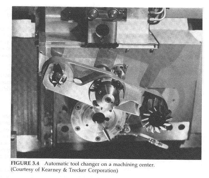 |
| Click inside to open a larger image of Figure 3-4 Automatic tool changer on a machining center-> |
![]()
Spindle speed selection involves two items: (1) knowing what speed is correct for a given situation, and (2) knowing how to specify that speed in an N/C program. Some N/C machines feature programmable spindle speed selection; other N/C machines require the spindle speeds to be manually set and manually changed.
Programmable spindle speed capability requires an N/C machine to have a variable-speed motor, usually a DC motor with an electronic tachometer to feed back spindle RPM information to the controller. This complexity is usually restricted to the higher priced N/C machines, such as machining centers and turning centers.
Smaller N/C machines usually have single-speed AC induction motors. Speed changing is manually achieved by changing V-belt pulley positions, shifting a gearbox, or shifting a variable-speed pulley drive.
The format for encoding the spindle speed depends upon the N/C machine being programmed. If the spindle speed format for a particular machine is S40, the address word S is followed by four digits to the left and zero digits to the right of a decimal point. Thus a spindle speed of 3200 RPM would be encoded S3200; 320 RPM = S0320; 32 RPM = S0032.
Whether the spindle speed selection is encoded into the program or manually set by the N/C operator, the N/C programmer must determine what the spindle speed should be. The speed is then either encoded into the program or specified to the N/C operator, to be adjusted at appropriate points in the program, usually in conjunction with cutting tool changes.
The correct spindle speed is determined by many variables that can interact and become very complex. Some of the variables defy measurement, so we'll reduce these to only three parameters for "normal" conditions (whatever "normal" means).
The first two of these parameters relate to the the number one enemy of cutting tool life: HEAT. The first parameter that determines the amount of heat generated is the relative velocity between the cutting edge and the workpiece. The velocity in turn is a function of the cutter or workpiece diameter, whichever rotates. For a given RPM, the larger the diameter, the higher will be the velocity and the greater will be the heat generated.
The second parameter concerns the kind of material being cut, specifically its machineability. The more difficult a material is to machine, the more heat will be generated and the higher will be the temperature of the cutting tool. Rubbing friction also generates some heat, but it is relatively minor, unless the cutting edge is especially dull.
The third parameter concerns the ability of the cutting tool to resist heat--or more correctly, elevated temperature. The kinds of cutting tool materials commonly used, in the order of their ability to withstand elevated temperatures, are high-carbon steel, high-speed steel, cast alloys (such as Stellite), tungsten carbide, and ceramic oxide. Cutting tool materials seem to have a threshold temperature above which they quickly loose their ability to maintain a sharp cutting edge. Their approximate threshold temperatures are shown in Table 3.1
| Table 3.1 Cutting Edge Breakdown Threshold Temperatures for Various Cutting Tool Materials |
|
|---|---|
| Cutting Tool Material | Threshold Temp. (° F) |
| Plain High Carbon Steels | 300 |
| High Speed Steel (HSS) | 1100 |
| Cast Alloys | 1300 |
| Tungsten Carbide | 1600 |
| Titanium Carbide | 1600 |
| Ceramic Oxides | 2100 |
 In addition, the following factors can affect the RPMs.
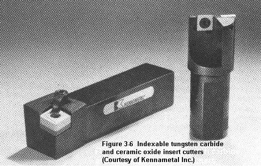 The generation of heat is no problem if the heat can be carried away as fast as it is generated, as by using a coolant. Likewise, elevated cutting tool temperatures are OK if the cutting tool material has an elevated threshold temperature, as with the carbide and ceramic cutting tools (Figure 3.6).
One must be cautious about cutting speeds that are sufficiently high as to overheat the workpiece, causing it to expand. Upon cooling, the workpiece will shrink and possibly be undersize. Furthermore, overheating can degrade the heat treatment of some workpiece alloys.
Table 3.2 shows cutting tool velocities (cutting speeds) that can be safely used for most "average" conditions with high-speed steel cutting tools. Consult manufacturer's data sheets for other cutting tool materials and cutting tools with special coatings, etc.
| Table 3.2 Cutting Speeds for Various Materials in Surface Feet per Minute* * These figures are approximate maxima; lower velocities are not detrimental to tool life, only to economics. |
||
| Workpiece Material | Cutting Tool Material | |
|---|---|---|
| High-Speed Steel | Tungsten Carbide | |
| Superalloys | 10 to 25 | 30 to 75 |
| Tool steels | 25 to 75 | 75 to 200 |
| Stainless steels | 25 to 75 | 75 to 200 |
| High-carbon steels | 25 to 75 | 75 to 200 |
| Alloy steels | 25 to 75 | 75 to 200 |
| Medium-carbon steels | 50 to 100 | 150 to 300 |
| Low Carbon Steels | 100 to 150 | 300 to 450 |
| Leaded mild steels | 200 to 400 | 500 to 1000 |
| Yellow brass | 300 to 750 | 1000 + |
| Aluminum | 500 to 1000 | 1000 + |
It is important to understand that there are a lot of variations in cutting tool materials and in workpiece materials. The results of the following equation may have to be revised upward or downward to suit the specific conditions of each machining situation. But the numbers should at least "be in the ball park."
| Spindle Speed (in Revolutions Per Minute or RPM) |
= | Cutting Tool Velocity (in surface Inches per Minute) ------------------------------------------------------ Circumference of Cutter or Workpiece (in Inches) |
Cutting tool velocity (cutting speed) is normally expressed in feet per minute rather than in inches per minute. The circumference of a cutter or workpiece is its diameter * pi (3.14159). (The "*" means multiply.) Thus the equation can be restated as:
| RPM | = | Cutting Tool Velocity (in SFPM) * 12 --------------------------------------- Diameter (in Inches) * 3.14159 |
| where SFPM stands for surface feet per minute. | ||
By rounding the value of pi down to 3 and "canceling" it into the 12, the 12 becomes 4 and the equation can be restated in a more simplified form and "burned" into one's brain, as all experienced programmers do
|
For example, a 1.500 inch diameter 2-flute HSS end mill cutting in half-hard yellow brass with a cutting tool velocity of 500 SFPM (Table 3.2) would require a spindle RPM of 500 * 4/1.5 = 2000/1.5 = 1333 RPM. This figure would need to be decreased if the depth of cut was deep and/or the feedrate was high. It could be increased for a light finish cut or if coolant was used.
Some N/C lathes are capable of being programmed to maintain a constant cutting velocity rather than a constant RPM. When facing, cutting contours and tapers, etc, the spindle speeds up as the cutter moves along the lathe's X-axis (cross slide) toward the spindle axis and slows down as the cutter moves away from the spindle axis. The programmer specifies the cutting velocity in SFPM. The controller constantly monitors the distance between the spindle axis and the cutter and changes the RPM as needed.
Cutting tool life can be significantly extended in many instances by special treatments applied to the cutting edge, such as a heat treatment called nitriding, or surface coatings such as titanium nitride.
Except for those rare few souls that write N/C programs for the sheer joy of it, the ultimate purpose of owning, programming, or operating an N/C machine tool is to make a buck. The buck is made by performing a service or making a product better and at lower cost than the competetion can do it.
One of the major factors in machine tool economics is time. The longer it takes to do something, the more it costs. The length of time it takes to make a piecepart using N/C is a direct function of the feedrate used. The slower the feedrate, the longer it will take to run the piecepart. Other factors, such as making unnecessary cutting passes, are also important, but using the correct feedrate (and spindle speed) is perhaps the most important factor in the economics of N/C. The optimum feedrate is one that maximizes the Material Removal Rate (MRR) without stalling the spindle or breaking the cutter.
The classic method of determining the feedrate is to decide upon a chip load (how thick a chip you wish each tooth to peel off), typically from 0.003 to 0.020 inch. Then calculate what the spindle speed should be. Next, count the number of teeth on the cutter. Then multiply the three together:
Feedrate (IPM) = chipload (IN) * RPM * teeth
The results of that equation, while adequate for most manual machining operations, is often inadequate for high spindle horsepower N/C machines.
In addition to being uneconomical, a feedrate that is too slow can hasten cutting tool failure. As each tooth peels off a chip, it also work hardens the workpiece surface. The depth of this workhardened layer can range from a few millionths of an inch to over a thousandth of an inch. If the feedrate is too slow, the cutting edge of each tooth can be cutting through the workhardened layer (dulling the cutting edge) instead of slicing beneath the layer.
A feedrate that is too high can stall the spindle or break the cutter--or both. The feedrate that is required to stall the spindle depends upon the following factors:
The geometry of the cutter is a minor factor and can be ignored. Good machining practice presupposes the cutter is sharp, so that factor can be ignored.
For milling, the material removal rate (MRR) can be calculated as follows: MMR = depth of cut * the width of cut * spindle speed * the feed per tooth (chip load) * the number of teeth * the spindle speed (RPM).
For lathe cuts, the MRR is the product of the mean workpiece circumference * the depth of cut * feedrate (in inches per revolution) * the spindle speed. The mean workpiece circumference is the circumference halfway down the depth of the cut.
For drilling, the MRR is the product of the area of a circle the diameter of the drill (drill diameter squared * pi/4) * the feedrate in inches per revolution * the spindle speed in RPM.
The horsepower required to run the spindle is the product of the Material Removal Rate (MRR) * the Material Machining Factor (MMF). The MMF, a function of the machineability rating of the workpiece material, is shown in Table 3.3.
| Table 3.3 Material Machining Factors (MMF) |
|
|---|---|
| Material | MMF |
| Aluminum | 0.12 |
| Brass | 0.4 |
| Low-carbon steel | 1.25 |
| High-carbon & low alloy steel | 1.5 - 1.9 |
| Stainless and tool steels | 1.8 - 2.2 |
| Superalloys | 2.5 - 5.0 |
For example, suppose a 1-inch-diameter end mill was making a 1-inch-deep cut in low-carbon steel with a feedrate of 10 inches per minute (IPM). The MRR is 1 (depth) * 1 (width) * 10 (IPM) = 10. Table 3.3 shows low-carbon steel has an MMF of 1.25. Thus, it would require 10 (MRR) * 1.25 (MMF) = 12.5 HP to drive the spindle. If the spindle was driven with a 5 HP motor, it could stall and perhaps break the cutter. The feedrate (or depth of cut) would have to be reduced to lower the MRR, so a 5 HP or lower load was placed on the spindle.
Since:
HP = MRR * MMF
and
MRR = depth of cut * width of cut * feedrate
it follows that:
HP = MMF * depth of cut * width of cut * feedrate.
Thus,
| Feedrate | = | HP --------------------------------------- MMF * depth of cut * width of cut |
In the previous example, if the spindle motor were 5 HP
| Feedrate | = | 5 HP --------------------------------------- 1.25 (MMF) * 1 (depth) * 1 (width) |
= | 4 IPM |
| Per tooth chip load | = | feedrate (IPM) --------------------------------------- spindle RPM * cutter teeth |
Assuming a spindle speed of 400 RPM and a 2-flute cutter,
| Chip load | = | 4.0 IPM --------------------------------------- 400 RPM * 2 teeth |
= | 0.005 inch per tooth |
Suppose in the previous example the workpiece material is changed to aluminum (with an MMF of 0.12). Spindle horsepower is 5. Spindle RPM is 4000.
| Feedrate | = | 5 HP --------------------------------------- 0.12 (MMF) * 1 (depth) * 1 (width) |
= | 41.7 IPM |
| Chip load | = | 41.7 IPM --------------------------------------- 4000 RPM * 2 teeth |
= | 0.0052 inch per tooth |
![]()
![]()
Jump to Contents Page
Updated Nov. 26, 2001
Copyright © 1988, 2001 by George Stanton and
Bill Hemphill
All Rights Reserved