| Paper Tape | Binary Coded Decimal |
|---|---|
| N/C Tape Codes | Parity: Which Code is Which? |
| Hardware | N/C Tape Readers |
| Magnetic Tape | Review Questions |
The method used to load an N/C program into a controller depends on whether the controller is one of the later models that has its own memory into which the entire program can be loaded, or whether it is one of the earlier models that must read an encoded paper or magnetic tape and execute the commands one block at a time.
If the controller is a later model with its own built-in memory (a CNC type of N/C machine), the program can usually be loaded into the controller by one of three methods. The first method is by keying in the program directly into the controller through the controller's keyboard. The problem with this method is that it ties up a multithousand dollar controller and machine tool while the program is being keyed in one command at a time. Obviously, the CNC machine cannot be machining workpieces while a programmer is keying in the program. (In effect the CNC machine is being used as a very expensive data-entry terminal.)
The second method of loading a program into a CNC's memory is to connect the controller to a computer that contains the previously written program. This can be done if the computer can output the program in the form of ASCII (or EIA) characters (more on that later) and if the computer and controller are each equipped with a means to be connected together, such as a serial port (sometimes referred to as a RS-232-C serial interface port or communications port). By setting the proper communications parameters (sometimes called communications protocols), the program can be transfered or downloaded from the computer to the CNC controller.
Communications parameters usually include the data transmission rate in characters per second (called baud rate); the number of bits per character; whether each character must have an even or odd number of bits (parity); and the handshaking method (software controlled, hardware controlled, or no control). The method of setting the parameters is usually by a gang of small pencil-actuated switches called DIP switches. Occassionally, the parameters are software controlled.
The third method is to connect the CNC controller to a paper tape punch/reader or magnetic tape recorder or magnetic floppy disk through the serial port. The program, previously encoded on the tape or disk, is "read" into the CNC's memory. As with the computer, the communications protocols must be properly set for the reader and controller.
If the N/C controller is one of the earlier models that has a built-in tape reader to read a paper or magnetic tape, reading and executing the commands one block at a time, the program must be encoded in the tape in some format the controller recognizes.
![]()
 In the earlier N/C systems, the most commonly used program storage medium was paper tape. A paper tape is one inch wide. As shown in Figure 4.1, the tape is considered to have eight tracks (called channels) that run along the length of the tape. The channels are numbered 1 through 8 from right to left. Arrays consisting of 1 to 8 holes are punched across the width of the tape. (Small holes between the third and fourth channels are for the tape drive sprocket teeth; they have no symbolic meaning.) Some channels may have a hole in the array; other channels may not. Each of the across-the-tape array of holes is spaced 1/10 inch apart along the length of the tape and corresponds to an alpha character, a numeral, or some other symbol. Which character each array represents is determined by which channels are punched and which are not.
Click inside image to open a much
larger image in a new browser window ->
![]()
The first four of the eight channels (right to left) have numerical significance. They are assigned numerical values based on the binary (base 2) number system. The numerical values of channels 1 through 4 are 1, 2, 4, and 8 respectively. Channel 1 has a numerical value of one (2 to the zero power); channel 2 has a numerical value of two (2 to the first power); channel 3 has a numerical value of four (2 to the second power); and channel 4 has a numerical value of eight (2 to the third power).
The numerical value of an array across the tape is the sum total of the value of the channels 1 through 4 in which holes are punched. For example:
| A hole in channel 1 only = 1 A hole in channel 2 only = 2 A hole in channels 1 and 2 = 1 + 2 = 3 A hole in channel 3 only = 4 A hole in channels 1 and 3 = 1 + 4 = 5 A hole in channels 2 and 3 = 2 + 4 = 6 A hole in channels 1, 2, and 3 = 1 + 2 + 4 = 7 A hole in channel 4 only = 8 A hole in channels 1 and 4 = 1 + 8 = 9 A hole in channel 6 only (or 5 and 6) = 0 |
![]()
There are two popular code systems in wide use for encoding N/C programs on paper (and magnetic) tape. One code is called the ASCII code (ASCII stands for the American Standard Code for Information Interchange). The ASCII code is also called the RS-358 code and the ISO (International Standards Organization) code. The other code is called the EIA code (EIA stands for the Electronic Industries Association). The EIA code is sometimes called the RS-244 or the BCD (Binary Coded Decimal code, which is a misnomer, as both the EIA and ASCII codes are binary coded decimal).
The numerals 1 through 9 are the same in both the EIA and ASCII codes. Both codes add holes in channels 5, 6, and/or 7 to convert numeral characters to alpha characters and other symbols, but not the same way. The additional hole(s) used is (are) different for the two codes. As shown in Figure 4.1, for example, the EIA code alpha character W consists of the numeral 6, with an additional hole punched in channel 6. The ASCII W is the numeral 7, with additional holes punched in channels 5 and 7. EIA uses channel 8 for only one purpose--to represent the End Of Block (EOB) character. ASCII uses what would be the numeral 13 (channels 1, 3, and 4) for the EOB character. The ASCII code makes provision for both capital and lowercase alpha characters; the EIA code does not provide for lowercase characters. Certain characters, like the percent sign, parentheses, and the colon, exist in the ASCII code but not in the EIA code.
![]()
Each code is designed so that every character (array across the tape) in that code will have either an odd number of holes (EIA) or an even number of holes (ASCII). This characteristic is called parity. Initially, each character will have either an even number or an odd number of holes punched, depending on how many punched holes are required for each character.
For example, the numeral 1 requires a hole punched in channel 1, an odd number of holes. The numeral 3 requires holes punched in channels 1 and 2, an even number of holes. The EIA code adds an extra hole (in channel 5) to all characters having an even number of holes. With this extra hole added to the even-hole characters, all EIA characters then have an odd number of holes. This is called odd parity. The ASCII code adds an extra hole (in channel 8) to all characters having an odd number of holes. With this extra hole added to the odd-hole characters, all ASCII characters then have an even number of holes. This is called even parity.
The reason for having parity is that it is possible for a tape punch to miss punching a hole in an array. This would change the parity of that character from odd to even or vice versa. It would also change the meaning of that array to some other character, possibly making the entire program fail. The N/C controller, set to accept either EIA or ASCII characters, will expect each ASCII or EIA character to have its certain parity. If it finds a character with the wrong parity (called a parity error), it knows something is wrong and it stops dead in its tracks! It is then up to the programmer to examine the tape (by running it through a tape reader/printer) and correct the error.
It is not necessary for an N/C programmer to be able to directly read the ASCII or EIA characters punched on a paper tape. Electronic/mechanical tape readers do that. However, in order to read an existing tape into a microprocessor for editing, it may be necessary to set the system to read the particular code used on the tape. A system that receives ASCII coded characters when it is set to expect EIA characters may have a nervous breakdown. Therefore, the programmer must be able to examine a punched tape and determine whether the code is ASCII or EIA. This is done by simply counting the holes in several arrays. If the number in all arrays is an even number, the code is ASCII; if all the arrays are odd parity, the code is EIA.
![]()
 Hardware
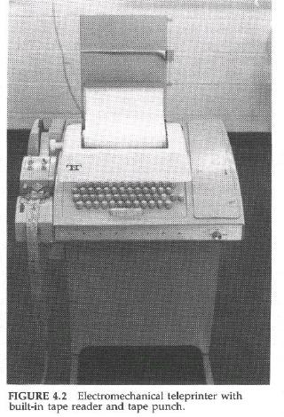
The hardware required to encode a program into a paper tape can range from an electromechanical Teletype terminal, with a built-in tape reader and a tape punch, to micro- and larger computers. The electromechanical type (Figure 4-2) punches a hole in the tape each time a key on the keyboard is depressed. If the wrong key is depressed, the wrong character becomes punched into the tape. Fortunately, there is a way to back the tape up and delete the error. Depressing the delete key on the teleprinter keyboard punches holes in all eight channels. Tape readers recognize this as a "delete" character and ignore it.
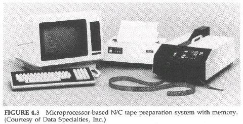 The more sophisticated N/C tape preparation systems are microprocessor-based and feature a memory. Some systems consist of an ordinary microcomputer (with a CRT screen display) connected to a a tape reader/punch and a printer (Figure 4-3). Other systems use a typewriterlike teleprinter connected to a combination microprocessor and tape reader/punch.
 With either system, the program is typed into the memory, or an existing N/C tape is read into the memory via the tape reader. The program can then be printed from the memory and scanned for errors. Errors can then be corrected in the memory. The content of blocks can be changed and they can be moved to new locations in the program. New blocks can be inserted and unwanted blocks deleted. Some microprocessor-based tape-preparation systems can, for example, change all of the +X character "strings" to X+ strings with a single command (called a global mass substitute command). After all of the errors have been corrected, all changes made, and the program is the way you want it, then the program is punched on tape and also printed out. The printout is called a hardcopy (Figure 4-4).
Click inside the image
to open an ASCII file
of a typical N/C program
in a new browser window ->
![]()
A photoelectric tape reader (Figure 4.5) is a device that incorporates an array of eight photocells over which is situated a light source. The array of photocells is arranged to correspond to the eight channels of an N/C paper tape. When a blank paper tape is inserted into the tape reader and passed over the photocells, it blocks off the light to the photocells, deenergizing or turning them off. If the tape channels contains holes, the light passes through the holes and energizes the corresponding photocells. Each energized photocell sends a signal to the N/C controller, which the controller recognizes as characters according to the tape code it has been set to read.
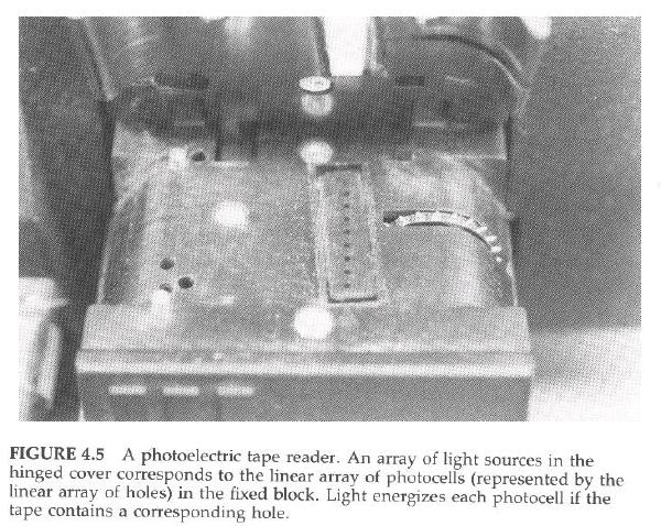
Some tape readers have very sensitive photocells and may sense light passing through the paper itself. Sometimes pinholes in the tape may be interpreted as strange characters, causing the controller to act as though the program were faulty. Such problems are cured by using particularly opaque tape, such as high-quality black paper tape or Mylar tape.
![]()
Some controllers, primarily used on large 4- and 5-axis mills, use magnetic tape instead of paper tape. Eight-channel EIA or ASCII characters are recorded as magnetic "spots" instead of holes. The array of spots is the same as the array of holes used on paper tape, but the arrays can be more closely spaced along the magnetic tape. Paper-tape hole arrays are spaced 10 per inch; magnetic spot arrays are spaced 800 to 4800 per inch. Obviously, it doesn't require much magnetic tape to accommodate rather lengthy programs.
Some CNC controllers use cassette magnetic tapes for storing N/C programs. A program can be loaded into a CNC controller from a magnetic tape, edited while in the CNC's memory, and output as a new program on the same or another cassette. Some cassettes can hold only one N/C program per side; others can hold dozens of programs, virtually eliminating the storage problem for paper tapes. Magnetic tapes can usually be read by the magnetic read head much faster than the paper tape reader's photoelectric reader. Recording an edited CNC program on magnetic tape is similarly much faster than punching a paper tape. A magnetic tape can be reused over and over, while a paper tape, once the program has been changed, winds up in a trash can.
Magnetic tapes have certain disadvantages over paper tapes. They can be demagnetized and lose their program information. Care must therefore be exercised to keep tapes away from magnetic fields. This is not always an easy thing to do in machine shop environments. Motors have magnetic fields, machinists have magnetic tools, and even workpieces can become magnetized, especially if they have been held by a magnetic chuck, such as those used on surface grinders. Magnetic tape read heads are also more sensitive than photoelectric readers to contamination, such as the abrasive dust and chemical and oil vapors that are common in machine shops.
Paper tapes can be easily labeled for identification purposes. Some microprocessor-based N/C tape-preparation systems can output holes on a tape that are patterned to resemble traditional alphanumeric characters. These are punched on the front end of the tape--the leader--to label the tape. Since these can be directly read by a person, they are called manreadable characters.
![]()
![]()
Jump to Contents Page
Updated Nov. 26, 2001
Copyright © 1988, 2001 by George Stanton and
Bill Hemphill
All Rights Reserved