- Start AutoCAD and open the test tube geometry file generated in
Assignment #2.8. Using the File->Save As menu choice,
save the part geometry file in AutoCAD Release 12 (i.e., R12) DXF format.
- Start Rhino 3D, create a new file (File->New with inch units), and import the
DXF file geometry into the TOP view.
- Using the Edit Layer
 command,
delete or turn off of any/all excess geometry (i.e., borders, title blocks, hidden lines, center lines, etc.). command,
delete or turn off of any/all excess geometry (i.e., borders, title blocks, hidden lines, center lines, etc.).
- Slightly widen the base of the test tube holder as follows:
- In the Top view, zoom in on the side view geometry (located above the bottom view geometry).
- Select the short (0.063" thickness) line at the end of one of the test tube holder's "feet."
- Use the "Zoom Selected" button
 to
further zoom in on this geometry. to
further zoom in on this geometry.
- With Ortho turned on, move this line horizontally slightly away from the center of the holder.
- Using the Fillet command with a radius of 0 (zero), extend the top and bottom of the feet
back to the edge moved in the above step.
- Zoom out and then repeat steps b-e for the opposite foot.
- Join the curves of the side view into one curve.
- Rotate the side view 90° pick the rotate point on the bottom edge of the feet,
set Ortho on, & use the Right view window when rotating.
- In the top view, move the side view geometry until it is slightly offset the "upper" edge
of the "bottom" view geometry.
- Extrude the rotated side view slightly beyond the other side of the "bottom view geometry.
Note how this test tube holder polysurface is oversized in both the X and Y axes. Ensuring that the basic extrusion
has no surfaces in common with the final shape will prevent Rhino from having difficulties when calculating the
Boolian differences later on due to overlapping surface areas and/or "singularities."
- On the same layer and Z-axis plane as the 2D bottom view geometry, create a closed set
of curves completely surrounding the bottom view geometry.
- If you haven't done so already, select the bottom view geometry (outside edges only) and join them into one curve.
- Selecting both sets of curves, vertically move them below the Z-axis plane.
- With both co-planer curves selected, extrude a solid "cookie cutter that extend above the top of the basic extrusion.
- Using the Solids->Difference command, subtract the "cookie cutter" from the basic extrusion.
- Position the 2D hole geometry in 3D space so that the curves are located
below the shaped test tube extrusion.
- Select the hole curves and extrude them above the test tube holder polysurface.
- Using the Solids->Difference command, "drill" the top and leg holes thru the test tube holder.
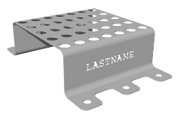
- In one of the solid sides, "punch out" your name.
- Set the appropriate parameters and render a perspective view of the test tube holder 3D model.
- If you haven't been doing so all along, save your work.
|