|
|---|
| Manually converting CNC tool paths from absolute (ABS) to incremental (INC)
coordinates using AutoCAD is a fairly straight forward process. One can compute the
X and Y coordinate differences between the start and stop points and—on arcs—also
compute the start to center points. The math can be simplified even more by putting the absolute
X and Y coordinate values into a spreadsheet and using the spreadsheet to calculate the
incremental differences. An
example Microsoft Excel spreadsheet
is availale for downloading. |
 An easier way (and, for simple
tool paths, a quicker way), is to draw straight lines (in the appropriate direction)
from the line or arc start & end points. The ΔX and ΔY values
displayed in the Properties window are simply the incremental X and Y
word address values. In the case of arcs, after drawing a straight line from the start the
center point, the Δ X and ΔY values shown in the Properties window will be the
I and J word address values. The Properties window can be toggled on and off by pressing the
Properties icon locate on the Standard toolbar (as shown). An easier way (and, for simple
tool paths, a quicker way), is to draw straight lines (in the appropriate direction)
from the line or arc start & end points. The ΔX and ΔY values
displayed in the Properties window are simply the incremental X and Y
word address values. In the case of arcs, after drawing a straight line from the start the
center point, the Δ X and ΔY values shown in the Properties window will be the
I and J word address values. The Properties window can be toggled on and off by pressing the
Properties icon locate on the Standard toolbar (as shown). |
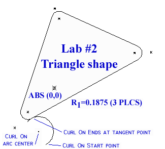
| In this example, the specified cutter center line tool path is the first shape of
lab #2, the filleted triangle with a curl-on and curl-off. The radius chosen
for the tritriangle's corner fillets is 0.1875 and the specified curl-on radius is 0.375. While any
tangent point on the triangle's tool path could be used for the curl-on point, the point chosen in this
example is the beginning of the lower left hand fillet arc. The toop path direction will be around the
triangle working clockwise. |
 |
| After the tool path geometry is drawn, the next step is to find the incremental
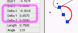
distance from the start point to the end point of the curl-on arc. Do this by drawing a line from
the arc start to the arc end. |
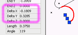
Put these two values into the I and J word address
registers as shown:
N1020 G03 G91 X-0.3618 Y0.6570 I-0.1809 J0.3285
If necessary, a cutter feed rate can be specified within the block. |
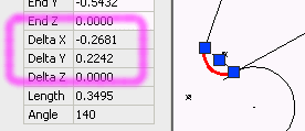
The process is now repeated for the next programmed entity (e.g., the lower left hand fillet
arc). Erase the previous line, draw a line new from the fillet arc start to the fillet ard end point,
and transfer the new ΔX and ΔY
data into the next program block.
ΔXstart to end = -0.2681

ΔYstart to end = 0.2242 |
 |
Place these two incremental values into the next blocks'
X and Y word registers as shown:
N1025 G02 G91 X-0.2681 Y0.2242 I_____ J______ |
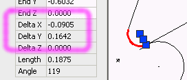
Erase the current line and draw another from the fillet arc start point to the fillet arc center point.
The ΔX and ΔY values for this line are the incremental I and J values:
	ΔXstart to ctr = -0.0905

ΔYstart to ctr = 0.1642 |
 |
Take these two new values and put them into the I and J word address
registers as shown:
N1025 G02 G91 X-0.2681 Y0.2242 I-0.0905 J0.1642 |
The next programming block is a straight line from the end point of the 1st fillet arc to the start point
of the 2nd fillet arc. Getting the incremental values for this shape is as simple as
eraseing the previous line, selecting the target line, and reading off the ΔX and ΔY values.
ΔXstart = 0.7926

ΔYend = 2.3471
As always, ensure that the line is drawn in the direct of the desired tool travel; otherwise use the negative ΔX and
ΔY values. |
 |
Place these two values in the next blocks' X and Y registers as shown:
N1030 G01 G91 X0.7926 Y2.3471 |
 |

 An easier way (and, for simple
tool paths, a quicker way), is to draw straight lines (in the appropriate direction)
from the line or arc start & end points. The ΔX and ΔY values
displayed in the Properties window are simply the incremental X and Y
word address values. In the case of arcs, after drawing a straight line from the start the
center point, the Δ X and ΔY values shown in the Properties window will be the
I and J word address values. The Properties window can be toggled on and off by pressing the
Properties icon locate on the Standard toolbar (as shown).
