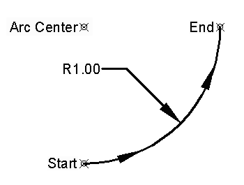
Whenever the Crusader is given a command to cut a two dimensional (2D or 2 axis) arc, it will assume that the current tool location is the starting point of that arc. Obviously, you should therefore make sure that the current tool point is located where you want the arc to begin. Thus, each circular interpolation statement must contain the X & Y axis, X & Z axis, or Y & Z axis locations of
The Crusader can cut 2D arc paths that pass through quadrant lines (0°, 90°, 180°, or 270°) in a single command; arc sector angles may be programmed up to 360 degrees.
Although the Crusader II can be programmed to cut arcs operating in the absolute positioning mode (G90), it is often simpler to use the incremental mode (G91).
Enter the arc center location BEFORE the arc end location. (Opposite order from RS-274-D format.)
 to toggle LED on, then toggle direction
 or
or
 as required, and press
 .
. .
. .
.
 .
.| Example: Program a 90 degree 1" radius arc counterclockwise from the 6:00 to 3:00 o'clock position at 15 IPM (see Figure 1). | |
| Event | Press the following keys (Toggle as required to activate) |
|---|---|
| 1 | 


 |
| 2 | 

 |
| 3 | 


 |
| 4 | 


 |
| 5 | 
 |

Figure 1 - Circular Interpolation
Enter the arc end point (X-Y-Z) BEFORE the arc center point (I-J-K). (Opposite order from Anilam format.)
| Example: Program a 90 degree 1" radius arc counterclockwise from the 6:00 to 3:00 o'clock position at 15 IPM (see Figure 1 above). |
| N0001 G03 G91 X1. Y1. I0 J1. F15. [EOB] |
|---|
| where [EOB] is "End of Block" or the basic text end of line. |
Copyright © 2003 George C. Stanton & Bill Hemphill
All Rights Reserved
Last updated on Jan. 21, 2003 by Bill Hemphill