Like all CNC controllers, the Anilam Crusader II has a number of built in, pre-programmed subroutines called "canned cycles." The canned cycles covered in this chapter are routines for Axes Scaling (G53) and X & Y-axis routines for creating rectangular pockets, circular pockets and bolt circles. For details on the other advanced programming capabilities supported by the Crusader II controller, please reference the applicable pages of the Crusader II Programming Manual.
The canned cycles in Chapter 9 are Z-axis routines for creating
drilled, countersunk, counterbored, or bored holes.
All Crusader II canned cycles use the controller's variable registers to hold the various data parameters (user programmed and internal)
required to execute the command. For more information on variable register useage, see
Chapter 5 and Chapter 6 .
In the G53 Scaling canned cycle, allows the programmer to scale the X, Y, &/or Z axes to proportionally change the programmed part size.
The G53 scaling command is modal and requires a G54 command to cancel. Additionally there are two other factors to consider when using the G53 Scaling command:
Programming Requirements:
| Example: | |
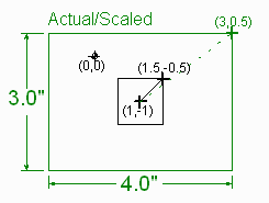
| Draw a 4x3 rectangle centered around the point (1,-1) using the uneven scale factors of 4 for the X axis and 3 for the Y axis. |  |
      EVENT   VAR.	VALUE 		COMMENT
------------------------------------------------------
	190	RPD ABS	X1 Y-1	$ Move to Rect. Center
	191	V11	1  	$ Scale Center X
	192	V12	-1  	$ Scale Center Y
	193	V13	0  	$ Scale Center Z
	194	V16	4  	$ Scale Factor X
	195	V17	3  	$ Scale Factor Y
	196	V18	1  	$ Scale Factor Z
	197	G53		$ Activate Scaling
	198	X1.5 Y-.5	$ Upper R/H corner
	199	Feed 2.0	$ Plunge Feedrate
	200	Z-.1		$ Plunge Z
	201	Feed 20.0	$ Transverse Feedrate
	202	INC F/R Y-1	$ Down R/H side
	203	X-1		$ Across bottom
	204	Y1		$ Up L/H side
	205	X1		$ Across top
	206	G54		$ Deactivate Scaling
Verbose format (with each variable commented):
	PROGRAM 						COMMENT
N169	G00 G90	 X1	Y-1			$ Move to Rect. Center
N170	G29 LV11=1				$ Scale Center X
N171	G29 LV12=-1				$ Scale Center Y
N172	G29 LV13=0				$ Scale Center Z
N173	G29 LV16=4				$ Scale Factor X
N174	G29 LV17=3				$ Scale Factor Y
N175	G29 LV18=1				$ Scale Factor Z
N176	G53					$ Activate Scaling
N177	G00 G90	 X1.5	Y-.5			$ Upper R/H corner
N178	G01 			Z-.1	F2.0	$ Plunge Z
N179	G91		Y-1		F20.0	$ Transverse Feedrate
N180		X-1				$ Across bottom
N181			Y1			$ Up L/H side
N182		X1				$ Across top
N183	G54					$ Deactivate Scaling
or
Compact format (without varible comments):
	PROGRAM 					COMMENT
N169	G29 LV11=1 V12=-1 V13=0		$ Set scale origin
N170	G29 LV16=4, V17=3, V18=1		$ Set scale factors
N171	G53					$ Activate Scaling
N172	G00 G90	 X1.5	Y-.5			$ Upper R/H corner
N173	G01 			Z-.1	F2.0	$ Plunge Z
N174	G91		Y-1		F20.0	$ Transverse Feedrate
N175		X-1				$ Across bottom
N176			Y1			$ Up L/H side
N177		X1				$ Across top
N178	G54					$ Deactivate Scaling
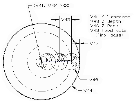
Capabilities: The G77 cycle circular pocket canned cycle can mill a pocket of any diameter and depth (within the range of the machine), taking as many depth passes (pecks) as desired. The pocket must have a radius larger than the cutter radius. Stock can be left for a finish pass at a different feedrate—or the finish pass can be omitted. Programmed parameters (i.e., those specified directly by the programmer) are specified in the command in the variable range V40 through V49.
For more information regarding the function of the variable registers V40-V49 used in programming the G77 canned cycle, see Chapter 5. For details regarding the canned cycle's user-specified and internal variable register useage, see the G77 table in Chapter 6
The G77 circular pocket canned cycle is a non-modal command.

Figure 8-1: G77 Circular Pocket Canned Cycle
Description of Action:
| Example: | |
| Mill a .625" deep circular pocket 3.5" DIA centered at X=1.5 Y=2.375 ABS. Use a .75" DIA 2-flute end mill (0.375" radius). Use 0.100" Z axis clearance over the workpiece and a 0.300 deep peck depth. Set the stepover value at 0.550 (i.e., approximately 70% of cutter diameter, to avoid leaving corner stubs). Leave 0.020" for a finishing pass. Finally, set the finish pass feedrate to be twice roughing feedrate (which is 10 ipm). | |
Verbose format (with each variable commented):
	N135	F10 			$ SET FEEDRATE
	N140	G29 LV40=0.100		$ VAR: Z CLEARANCE
	N141	G29 LV41=1.5		$ VAR: X ABS CENTER POCKET
	N142	G29 LV42=2.375		$ VAR: Y ABS CENTER POCKET
	N143	G29 LV43=0.625		$ VAR: POCKET DEPTH (Z)
	N144	G29 LV44=3.5		$ VAR: POCKET DIAMETER
	N145	G29 LV45=0.55		$ VAR: MAX XY STEPOVER
	N146	G29 LV46=0.300		$ VAR: MAX Z PECK / PASS
	N147	G29 LV47=0.02		$ VAR: FINISH PASS (SIDES AND BOTTOM)
	N148	G29 LV48=20.0		$ VAR: FINISH PASS FEEDRATE
	N149	G29 LV49=.75		$ VAR: CUTTER DIAMETER
	N150	G29 LV50=0		$ VAR: FINISH PASS FLAG (TRUE)
	N155	G77 			$ ACTIVATE CANNED CYCLE
or
Compact format (without detailed parameter comments):
	N135	F10 				$ SET FEEDRATE
	$ LOAD VARIABLE REGISTERS FOR CIRCULAR POCKET
	N140	G29 LV40=0.100 V41=1.5 V42=2.375 V43=0.625 V44=3.5
	N145	G29 LV45=0.55 V46=0.300 V47=0.02 V48=20.0 V49=.75
	N150	G77 				$ ACTIVATE CANNED CYCLE
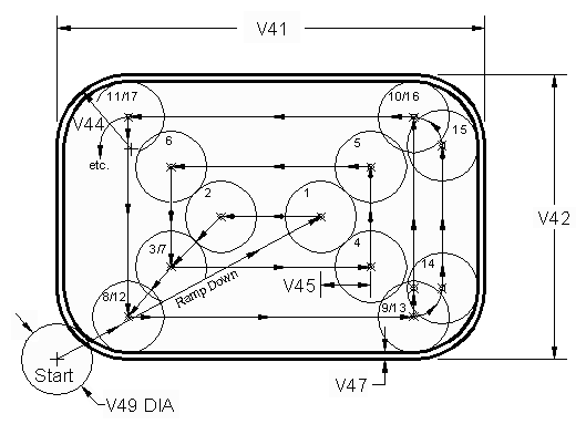
Capabilities: The G78 cycle rectangular pocket canned cycle can mill a pocket of any length, width, and depth (within the range of the machine), taking as many depth passes (pecks) as desired. The pocket can have corner radii larger than the cutter radius. Stock can be left for a finish pass at a different feedrate--or the finish pass can be omitted. Programmed parameters (i.e., those specified directly by the programmer) are specified in the command as variables V40 through V50.
For more information regarding the function of the variable registers V40-V50 used in programming the G78 canned cycle, see Chapter 5. For details regarding the canned cycle's user-specified and internal variable register useage, see the G78 table in Chapter 6
The G78 rectangular pocket canned cycle is a non-modal command.

Figure 8-2: G78 Rectangular Pocket Canned Cycle
Description of Action:
| Example: | |
| Mill a 6" X-axis by 4" Y-axis by 1.5" Z-axis pocket with 1" radius corners. Locate the (virtual) lower L/H corner of the pocket at X=-2.5 and Y=-1.25. Use a 1" DIA 2-flute end mill (0.5" radius). Use 0.100" Z axis clearance over the workpiece and a 0.375 deep peck depth. Set the stepover value at 0.700 (i.e., 70% of cutter diameter, to avoid leaving corner stubs). Leave 0.020" for a finishing pass. Finally, set the finish pass feedrate to be twice roughing feedrate (which is 10 ipm). | |
      EVENT   VAR.	VALUE 		COMMENT
------------------------------------------------------------------
	35	X	-2.5	$ Start X-axis
	36	Y	-1.25	$ Start Y-axis
	37 	FEED	10.  	$ Roughing feedrate
	38 	V40	.100 	$ Start height above the part
				$ (Z-clearance)
	39 	V41	6.  	$ X-axis length of pocket.
	40 	V42	4.  	$ Y-axis length of pocket.
	41 	V43	1.5 	$ Z-axis depth of pocket
				$ (excluding Z-clearance).
	42 	V44	1.  	$ Pocket's corner radius.
	43 	V45	.7 	$ Maximum X & Y stepover.
	44 	V46	.375 	$ Maximum Z-peck per pass.
	45 	V47	.02 	$ Finish pass stock (sides &
		 		$ bottom = same).
	46 	V48	20.  	$ Finish pass feedrate.
	47 	V49 	1.  	$ Cutter diameter.
	48 	V50 	0 	$ Finish pass indicator: set to 0
				$ if a finish pass is required or
				$ 1 if no finish pass is
			  	$ required.
	49 	G78		$ Activates the canned cycle.
Verbose format (with each variable commented):
	N070	G00 G90 X-2.5	Y-1.25	$ START POSITION (LWR L/H CORNER)
	N075	F10 			$ SET FEEDRATE
	N080	G29 LV40=0.100		$ VAR: Z CLEARANCE
	N081	G29 LV41=6.0		$ VAR: POCKET LENGTH (X)
	N082	G29 LV42=4.0		$ VAR: POCKET WIDTH (Y)
	N083	G29 LV43=1.5		$ VAR: POCKET DEPTH (Z)
	N084	G29 LV44=1.0		$ VAR: CORNER RADIUS
	N085	G29 LV45=0.7		$ VAR: X & Y STEPOVER
	N086	G29 LV46=0.375		$ VAR: MAX Z PECK / PASS
	N087	G29 LV47=0.02		$ VAR: FINISH PASS (SIDES AND BOTTOM)
	N088	G29 LV48=20.0		$ VAR: FINISH PASS FEEDRATE
	N089	G29 LV49=1.0		$ VAR: CUTTER DIAMETER
	N090	G29 LV50=0		$ VAR: FINISH PASS FLAG (TRUE)
	N095	G78 			$ ACTIVATE CANNED CYCLE
or
Compact format (without detailed parameter comments):
	N070	G00 G90 X-2.5	Y-1.25		$ START POSITION (LWR L/H CORNER)
	N075	F10 				$ SET FEEDRATE
	$ LOAD VARIABLE REGISTERS FOR RECT POCKET
	N080	G29 LV40=0.100 V41=6.0 V42=4.0 V43=1.5 V44=1.0 V45=0.7
	N085	G29 LV46=0.375 V47=0.02 V48=20.0 V49=1.0 V50=0
	N090 G78 				$ ACTIVATE CANNED CYCLE
In the G79 Bolt Circle canned cycle, holes are equally spaced between the first and last holes. Progression about the bolt circle is counterclockwise (clockwise rotation can be achieved by mirroring). The positions for the first and last holes are stated relative to the angle zero (3:00 o'clock) position, counterclockwise.
The G79 canned cycle is a non-modal (i.e, one-shot) cycle; however the required G80-series cycle--activated to yield Z-axis drilling motion--is modal and requires a G80 command to cancel.
Programming Requirements:
| Example: | |
| Peck drill (G83) 12 equally spaced holes of 1/4" diameter and 3/4" deep using a feedrate of 3.7 IPM and a peck of 0.25". The holes will be located around a 4.500" diameter bolt circle with its center located at (ABS) X=2.75 and Y=3.6875 . The the first hole is to be 17 degrees from the angle zero (3:00 o'clock) position. | |
      EVENT   VAR.	VALUE 		COMMENT
------------------------------------------------------------------
	170	V20	3.7 	$ Z-stroke feedrate (IPM)
	171	V21	.100  	$ ABS Z clearance plane height
	172	V23	.25 	$ Peck increment
	173	G83		$ Activate canned peck drill cycle.
	174	Z	-.75 	$ ABS Z-depth of all holes.
	175	V11	2.75  	$ Bolt circle center ABS X-location
	176	V12	3.6875 $ Bolt circle center ABS Y-location
	177	V13	17 	$ Index angle to rotate bolt circle pattern CCW
	178	V15	0  	$ Angle location of first hole
				$ (Negative values are OK.)
	179	V16	30 	$ Angle location of last hole.
				$ (Negative values are OK.)
	180	V17	12 	$ Number of holes
	181	V18	4.5 	$ Diameter of bolt circle
	182	G79 		$ Activate bolt circle canned cycle.
	183	G80		$ Deactivate G83
Verbose format (with each variable commented):
	PROGRAM 				COMMENT
N170 G29 LV20=3.7			$ Z-axis feedrate
N171 G29 LV21=.100			$ ABS Z-axis clearance
N172 G29 LV23=.25			$ Peck increment.
N173 G83				$ Activate peck drill cycle.
N174 G90 Z-0.75			$ ABS Z-depth of holes
N180 G29 LV11=2.75 			$ ABS X location of BC Ctr
N181 G29 LV12= 3.6875			$ ABS Y location of BC Ctr
N182 G29 LV13=17			$ Index angle (CCW rotation)
N183 G29 LV15=0 			$ Angle of 1st hole
N184 G29 LV16=30 			$ Angle of last hole
N185 G29 LV17=12 			$ Number of holes
N186 G29 LV18=4.5  			$ Diameter of BC
N190 G79 				$ Activate bolt circle canned cycle
N195 G80 				$ Cancel G83 Z-axis cycle
or
Compact format (without comments):
	PROGRAM 				COMMENT
N165 G29 LV20=3.7 V21=.100 V23=.25	$ Set peck drill parameters
N170 G83				$ Activate peck drill cycle.
N175 G90 Z-0.75			$ ABS Z-depth of holes
					$ Set Bolt Circle parameters
N180 G29 LV11=2.75 V12= 3.6875 V13=17 V15=0
N185 G29 LV16=30 V17=12 V18=4.5
N190 G79 				$ Activate bolt circle canned cycle
N195 G80 				$ Cancel G83 Z-axis cycle
Copyright © 2003-2007 George C. Stanton & Bill Hemphill
All Rights Reserved
Last updated on Dec. 7, 2007 by Bill Hemphill