| CAUTION Some illustrations may show products where safety equipment may have been removed or opened to clearly illustrate those products. Such safety equipment must be in place prior to operation. |
|---|
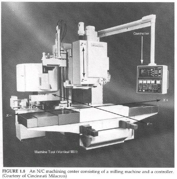
An N/C machine is a system composed of two major components (Figure 1.8) together with various auxiliary equipment. The two major components are (1) a machine tool such as a milling machine, drilling machine, engine or turret lathe, flame cutting machine, laser cloth cutter, or almost any other kind of machine that has a moveable cutter of some sort; and (2) a controller to direct the motion of the cutter. Auxiliary equipment may include programming hardware, such as a data-entry terminal, line printer, and tape punch. Other programming equipment might include a computer for computer-assisted N/C programming and an X-Y plotter for verifying the accuracy of the program before trying it on the N/C machine.
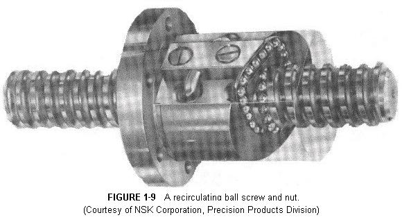
The machine tool portion of an N/C machine varies from its manually-operated counterpart in two very important respects. First, the N/C machine tool is usually more rigid, since deflection must be minimized; and second, the axes are usually actuated by means of ballscrews--a hardened-and-ground leadscrew with a recirculating ball bearing nut (Figure 1.9). The thread groove on the leadscrew is ground to exactly fit the balls with zero clearance. This eliminates the backlash that results from the clearance between the screw and nut found with ordinary acme thread leadscrews used on most manual machine tools.
Large N/C milling machines are called machining centers. They have automatic tool changers with magazines that may hold up to a hundred or more different tools. They often have a horizontal spindle. Some have a fourth and even a fifth axis. The fourth axis is a tiltable table built into the main table. The fifth axis is a rotary table mounted on the tiltable table. This permits a workpiece to be tilted and rotated for milling compound angle surfaces and machining holes at an angle to the sides.
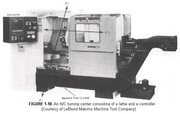
Large N/C lathes (Figure 1.10) are called turning centers. They have automatic tool changing and multi-station turret tool holders. They can perform contour turning, threading, drilling, boring, etc. operations.
![]()
| Feedback: Open vs. Closed Loops |
|---|
Back to Contents Page
Updated Jan. 9, 2002
Copyright © 1988-2002 by George Stanton and
Bill Hemphill
All Rights Reserved