Cutting tool motion axis commands tell the controller where to send the cutter. They may be incremental--telling the cutter where to go from where it is (G91), or absolute--telling the cutter where to go relative to the origin (G90). As previously discussed, cutter motion can be either point-to-point positioning (G00) at rapid travel; linear interpolation at feedrate (G01) for straight-line cutting; or circular interpolation at feedrate for cutting arc paths, either clockwise (G02) or counterclockwise (G03).
Linear cutter motion commands consist of simply entering the axis address word X or Y or Z (followed by a plus or minus sign if needed) and the axis destination of the cutter. If the preparatory command G00 is in effect, the motion will be at rapid travel and possibly follow a dogleg path, as discussed in Chapter 2. If the preparatory command G01 is in effect, the cutter motion begins at the current cutting tool point location and progresses in a straight line (at an angle for 2 and/or 3 axis commands), at whatever feedrate is currently active.
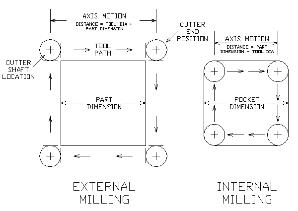
Cutter motion statements (X, Y, and Z axes) for milling are intended to guide the periphery of the cutter along the surface being machined. However, it is the point of the cutter, not its periphery, that has to be programmed. Cutter motion commands always tell the cutting tool point where to go. The tool point is the center of the cutter at the business end.
Therefore, unless the programmer is using CNC's tool offset capability (G41 or G42), each tool motion statement must be written to offset the cutter an amount equal to the cutter's radius, as illustrated in Figure 3.1.
Arc path cutter motion (circular interpolation) likewise involves programming the cutting tool point. The cutter's current location (the current tool point) is always understood to be the beginning point of an arc path. So the first thing to do is position the cutter where the arc is to begin. Next, regular X- and Y-axis commands are used to establish the location of the endpoint of the arc. This can be done in terms of either incremental distance (in the G91 positioning mode) or absolute coordinate location (in the G90 positioning mode).
In order to generate an arc path, the controller has to know where the center of the arc is located. This is sometimes called the arc center "offset." As shown in Figure 3.2(a), the address words I and J are used to identify these offsets.
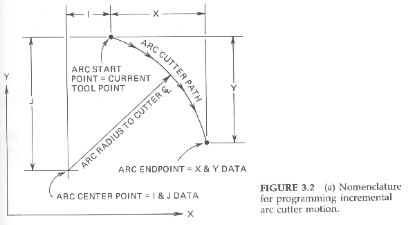
Figure 3-2(b) shows how the location of the arc center is stated incrementally relative to the arc start point (when in the G91 incremental mode).
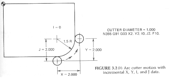
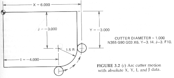
Figure 3.2(c) shows how the arc center's location is stated in terms of the arc center's coordinate location relative to the origin (when in the G90 absolute mode).
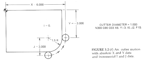
Note that some controllers require location of the arc center to be stated incrementally--relative to the arc start point, as shown in Figure 3.2(d), even if the positioning mode is G90 absolute.
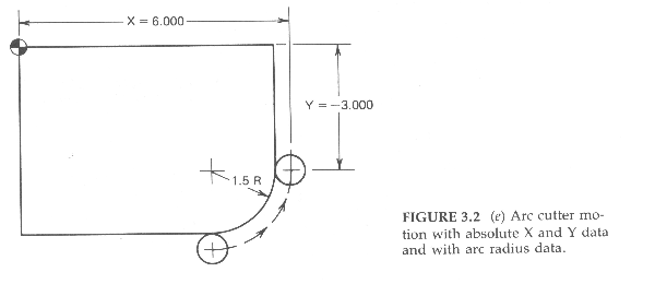
Some controllers can accept arc radius data directly (in the form of R commands), as shown in Figure 3.2(e), and do not require I or J commands. These controllers are capable of calculating the location of an arc's center if they know the arc's start point (the current tool point), the arc's endpoint (X and Y command), the arc's radius (the R command), and the arc's clockwise or counterclockwise direction (G02 or G03).
Arc paths are usually most easily programmed using the G91 incremental positioning mode. As shown in Figure 3.2 (b) above, the I command is the offset distance from the arc start point to the arc center parallel to the X axis. Likewise, the J command is the offset distance from the arc start point to the arc center parallel to the Y axis. Arcs that begin at the 12:00, 3:00, 6:00, or 9:00 clock positions--on quadrant lines--will have an arc offset (either the I or the J command) of zero value. Arc offset I and J commands that are of zero value usually do not need to be programmed and can be omitted.
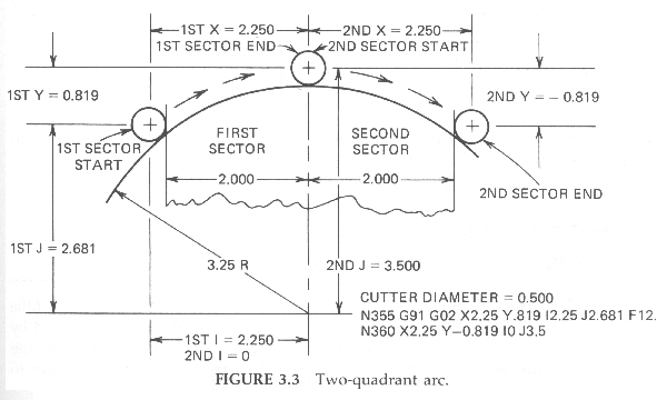
Many controllers cannot cut an arc that passes through a quadrant line in a single command. Arc paths that pass through one quadrant into another (Figure 3.3) must be "broken up" into two or more statements. An arc can be programmed to begin and/or terminate onquadrant lines, but not to pass through a quadrant line.
| Next: Miscellaneous Commands |
|---|
Back to Contents Page
Updated Jan. 9, 2002
Copyright © 1988-2002 by George Stanton and
Bill Hemphill
All Rights Reserved