The programmer has to make many decisions. Some are based on logic and others are arbitrary. One of the first decisions is which N/C machine to use to make the part. This decision may be predetermined (the shop may have only one N/C machine). It may be determined by the capabilities one machine may have that another machine may not have (such as tapping or a canned pocket milling cycle). It may be determined by the size or complexity of the workpiece, requiring a large or 4- or 5-axis N/C machine. Heavy cuts may have to be made that require a large N/C machine with lots of spindle horsepower. However, there's no sense in driving a thumb tack with a sledge hammer (unless it's a very large thumb tack), so the programmer will normally select the smallest N/C machine that has the size, horsepower, and capabilities needed to make the piecepart.
|
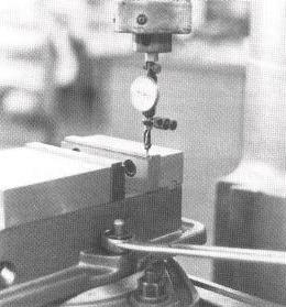
| Figure 5-02 Using a dial indicator to "indicate in" a vice aligning the fixed jaw parallel to an axis. |
The vise holds the workpiece firmly in contact with three locators:
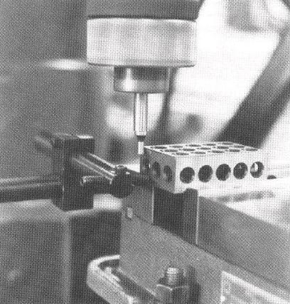 |
| Figure 5-02 An edge finder being used to align the spindle axis over the corner of a 1-2-3 block. The block's location in the vice is determined by the fixed jaw, parallels on which it rests, and the finger stop it touches. |
Because the vise's tightening screw is usually not in line with the workpiece, the moveable jaw on many vises will lift up slightly when tightened, lifting the workpiece off the parallels and cocking it. This can be avoided by using a vise designed to apply a downward force to the moveable jaw when it is tightened (Figure 5-03).
 |
| Figure 5-03 A vice mechanism to prevent the moveable jaw from lifting up when tightening. (Courtesy of Kurt Manufacturing Company) |
The vise must be kept in good condition, clean and free from surface bulges on the base that result from being dropped, hit with a hammer, or being tightened into a dirty table, with dirt and chips becoming hobbed into the base surface. (Always stone the base of a vise to remove such artifacts.)
Larger workpieces may be clamped directly to the table. A rail and a finger stop may be clamped to the table against which the workpiece can be positioned. The workpiece is then clamped in position with strap clamps.
Whatever method is used to hold the workpiece, the method should provide for each workpiece to be located in exactly the same place and not require the operator to "indicate in" each part with a dial indicator. The holding method must be secure so the part won't move or slip. Clamps must either be located where the cutter won't hit them, or the program must provide for an interruption so the operator can move the clamps when necessary.
![]()
Once the programmer has visualized the workpiece, decided on which N/C machine to use, and determined how the workpiece is to be held, the next step is to determine which cutting tools to use.
The main differences between High-Speed Steel (HSS) and Tungsten Carbide (WC) cutting tool materials are:
Generally, WC cutters with indexable inserts are preferred for N/C lathes. In addition to long life, they are available in a wide variety of sizes, shapes, and grades (combinations of toughness and wear resistance), and their shapes are uniform. Inserts are available plain, with preformed chip breakers, and with special coatings to extend their lives. With standardized uniform size and shapes, replacing an insert does not require reprogramming the lathe.
HSS cutters are preferred for milling the softer nonferrous metals, such as brass and aluminum alloys. WC milling cutters with replaceable inserts are usually preferred for ferrous metals (steel and cast iron) and the tougher nonferrous metals such as titanium and the superalloys.
Two-flute end mills have larger gullets (deeper flutes) and hence can hold more chips, which makes them better for heavy cuts (hogging). Four-flute end mills are more rigid so have less deflection, and have more cutting edges, which yield a smoother surface finish and higher feedrates. They are better for finishing cuts (Figure 5-04).
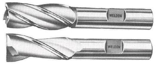 |
| Figure 5-04 Two-flute end mills have larger flutes. (Courtesy of The Weldon Tool Company) |
The diameter of an end mill to be used is often determined by the size of the inside corner radii to be machined. Generally, the programmer should use the largest standard fractional size (0.500 inch, 0.750 inch, 1.000 inch, etc.) that will get the job done in the fewest possible passes. However, keep in mind that
Ball end mills are used for milling complex surfaces (Z-axis contouring) and for full-radius grooves. Ball end mills cannot take heavy cuts without clogging and tend to deflect more than do blunt-end cutters. They are used for finish passes, after the bulk of material has been "roughed away" with a regular end mill. Generally they should be used with cutting oil or other lubricant to prevent chips from sticking to the flutes.
Drills usually cut oversize. Holes with a diameter tolerance of 0.003 inch or less should be reamed or bored to final size. A full-length (jobbers length) drill will not necessarily drill a hole where it is supposed to. Drills are flexible and may drift, following the path of least resistance. A drill will usually wander or "walk around" on the chisel point web before begining to penetrate into the workpiece. Therefore, a hole location must always be "spotted" with a short rigid stubby drill or center drill. Center drills and short drills are sufficiently rigid to prevent wandering when they start to penetrate. Center drills (standard 60-degree combined drill and countersink) are not recommended for N/C work, because their pilots are fragile; the flutes become easily clogged, causing the pilot to break off.
Undersize (reground) 2-flute end mills make excellent boring cutters for truing-up the location of a not-too-deep drilled hole prior to reaming. Deeper holes and holes that require a very smooth surface finish require the use of standard adjustable single-point boring cutters.
Reamers have shallow flutes that become easily clogged with chips. Therefore a reamer should remove as little material as possible. Drill the hole the next size (but at least 0.004 inch) smaller than the reamer. A reamer should be run no faster than one-half the drilling speed. Use a fairly heavy feed. A reamer, like a drill, will always follow the path of least resistance. Always use a cutting lubricant to prevent seizing.
Straight-fluted taps are not intended for machine tapping. They must be reversed every turn to break off the chip, otherwise the flutes will become clogged and the tap will break off in the hole. Machine taps have either a spiral point (like a negative spiral) to make the chips curl out ahead of the tap or they have positive spiral flutes to curl the chip out the top of the hole (Figure 5-05). When using spiral-pointed taps in blind holes, allow at least one to three tap diameters extra hole depth to allow room for the chips.
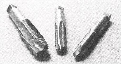 | |
| Figure 5-05 | The tap in the center, a straight 4-flute tap, is for hand tapping only because chips can lodge in the flutes. The two taps on either side are spiral-point taps for machine tapping. They curl the chip out ahead of the tap. (Courtesy of East Tennessee State University) |
All tapped holes should be countersunk to a chamfer diameter 1/32 inch larger than the tap diameter. This eliminates the burr that a tap would otherwise create at the top of the hole and it improves the appearance of the tapped hole. Countersink angles of 82 degrees and 90 degrees are most commonly used. They are available in multiflute and single-flute forms. Single-flute countersinks are less prone to chattering.
Two-flute end mills make excellent counterbores and spotfacers. They are less expensive than standard counterbores and, in an N/C mill, require no pilot.
![]()
| Next: Where to Change Cutters and Workpieces |
|---|
Back to Contents Page
Updated Jan. 23, 2002
Copyright © 1988, 2002 by George Stanton and
Bill Hemphill
All Rights Reserved