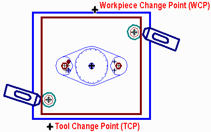
When changing cutters (manual tool change) and when changing workpieces, the location of the spindle and cutter is important. To avoid cuts on the fingers, hands, and arms from sharp edges, the operator should never have to reach over or around the workpiece to change cutters. Likewise, the operator should never have to reach around the cutter to change workpieces. So decide upon convenient locations for the spindle for each cutting tool and part change. When loading parts, the spindle should be behind the workpiece and to the left (if the operator is right-handed). When changing cutting tools, the spindle should be in front of the workpiece and to the right. An example plan view of a vertical mill setup showing the Workpiece Change Point (WCP) and Tool Change Point (TCP) is shown in Example 5-06.
 |
| Figure 5-06 Example locations of workpiece and tool change locations for a vertical mill. |
The X and Y origins should always be at the corner where the edge- and end-locating surfaces meet. When using a vise to hold the workpiece, one of these surfaces will be against the fixed jaw of the vise. The other surface will probably be in contact with a finger stop, such as shown in Figure 5.02. (If the workholder is a fixture with a pin that fits in a predrilled holed in the workpiece, that pin is locating the workpiece, and its center should become the X and Y origin.)
The programmer assumes the spindle axis is placed exactly over that corner location (using an edge finder--such as shown in Figure 5.02) or pin center (using a dial indicator) when the X- and Y-axis registers are zeroed. The Z origin surface is used for setting the tool length offset (touching off) for each cutting tool. It is usually the top of the workpiece (or rather a feeler gauge block the same thickness as the workpiece placed on the parallels or other surface the workpiece rests on).
Locational surfaces are those surfaces upon which the workpiece will be positioned for machining. As such, these surfaces affect the dimensional accuracy of the entire finished piecepart. The surfaces of castings and forgings (and saw cuts on bar stock) are usually not suitable for locational purposes. Their surfaces are often rough, lack flatness, and can vary considerably from one piecepart to another. Therefore, when machining on castings and rough sawn workpieces, the first surfaces to machine are the locational surfaces, for example the bottom, edge, and end surfaces of the workpiece. The workpiece may be held upside down in a vise or clamped directly to the N/C machine's table to machine the bottom and an edge. Then, after deburring, the workpiece is turned over, locating on the just-machined surfaces for the remainder of the machining operations.
One has to consider the effects that machining one feature can have on those that follow. For example, a hole might be drilled to a given depth and countersunk. Then the surface at the top of the hole is machined, decreasing the depth of the hole and machining away the countersunk chamfer. Normally, milled surfaces should be machined before holes are drilled.
Vertical surfaces can be machined with the periphery of the end mill at the same time the end of the cutter is milling a horizontal surface. But be aware that the heat generated by the peripheral milling can cause the cutter to become temporarily longer (thermal expansion), causing the end of the cutter to cut deeper than was intended. A spray mist or flood coolant should cure that problem. Also be aware that the spiral of the flutes on an end mill creates a downward thrust on the cutter that could cause the cutter to slip in the collet if it is not sufficiently tight. The cure to this problem is to always be sure the toolholder's collet is fully tightened.
Plan the sequence of machining operations to minimize the number of cutting tool changes. For example, do not rough machine one surface, then finish machine it, then rough machine the second surface, etc. Make all of the roughing cuts on all of the surfaces first, then change cutters and make all of the finish passes. Similarly, when drilling holes, first spot drill all of the locations, then drill all of the holes of one size, then drill the next size holes, then bore, ream, etc.
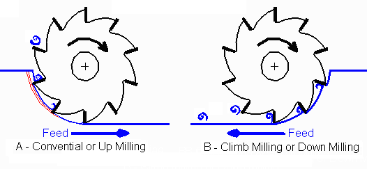
With apologies to the Bard of Avon, the next question that the programmer should ask concerns the direction of travel. The direction of workpiece feed in relation to the direction of rotation of the cutter is an important consideration in any machining operation due to tooling loading and surface finishing. Feeding the material in the opposite direction of the cutter rotation causes the resultant chip to begin thin and progressively cut deeper, an action that pushes the tool away from the workpiece. This direction of milling is called conventional milling or up milling and is common in manual milling operations where the any appreciable amount of backlash exists. Conventional milling is shown in Figure 5-07A. Feeding the material in the same direction as the cutting tool, resulting in a chip that start thick and tapers off, is called climb milling or down milling and is shown in Figure 5-07B. Although climb milling provides a better surface finish than conventional milling, the forces involved in climb milling are significantly higher as the cutting tool is literally pulling itself into the workpiece. Such forces can be catastrophic if the mill table uses old-style feed screw and nut as the cutter can suddenly shift an amount less than or equal to the backlash.
 |
| Figure 5-07 ( A ) Conventional (thin-to-thick) vs. ( B ) Climb Milling (thick-to-thin) |
Fortunately, because N/C mills have ball screws that have no backlash, it is advantageous to climb mill. End mills stay sharp longer and are less prone to "dig in" and undercut when climb milling. Climb milling produces better surface finishes because the chip is not carried around by the cutter and cold welded onto the finished surface, as conventional milling often does. Beware that side thrust on the end mill is greater when climb milling; hence (especially for longer end mills) cutter deflection may leave projections oversize and pockets undersize. This problem can be solved by making a semifinish pass in the conventional direction followed by a finish climb cut pass.
When machining horizontal surfaces using the end of the cutter, use a "stepover" that allows each pass to overlap the previous pass by at least 0.050 inch to avoid surface ridges between passes. To minimize deburring (an expensive hand operation), passes along the edge of the surface should be in a direction that prevents the cutter from generating a burr at the edge. The direction should be such that each tooth is engaging the workpiece along the edge rather than the inner region.
Many other "tricks of the trade" that can streamline the programming and operation of N/C equipment can be learned from shop personnel, foremen, and supervisors who, in addition to formal education, have been through the School of Hard Knocks.
| Next: Review Questions for Chapter 5 |
|---|
Back to Contents Page
Updated Jan. 24, 2002
Copyright © 1988, 2002 by George Stanton and
Bill Hemphill
All Rights Reserved