- Create one (1) 2D AutoCAD drawing of one of the the five (5) components of a U-clamp Assy. This drawing should be complete with dimensions, a border, title and revision blocks, and a filled-in Bill of Materials.
- Combine and format the other components' geometry into one (1) file suitable for export (i.e., a DXF file)
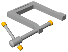
- Import the 2D geometry into Rhino 3D, extrude or rotate the various components and manipulate them into an assembled U-Clamp.
- Before rendering the model, set the Object Properties of the (2) caps and swivel to a brass-looking color
- Render your final drawing and save both the 3D model and at least one (1) rendered image.
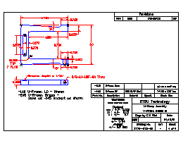
U-Frame, Details of; Rev B
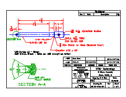
Screw, Details of
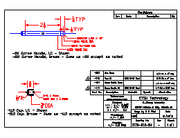
Handle & Cap, Details of
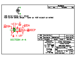
Screw Swivel, Details of