- the processes & tasks involved in creating 2D loft geometry;
- some of the basic processes involved in calculating desired geometrical cross sectional areas;
- creating and transforming loft geometry into surfaces; and
- converting the open ended surface(s) to a solid, watertight 3D model.
This assignment will walk you through the process of developing a simplistic solid model that smoothly transitions from a 2" x 2" square and—within a short, one (1) inch length—best matches the interior diameter of a standard PVC Schedule 40 pipe section .
- Within a new Rhino drawing (Small Objects - Inches), draw a 2" x 2" square around the origin (0,0,0).
 Use
Rhino to calculate an area measurement within the square:
- Select the 2D square geometry.
- From the Main Menu, choose Analyze->Mass Properities->Area.
- The calculated area (4.00 in2) appears in the command line box. (This value should come as no suprise.)
- Calculate the ideal target diameter of a circle with an enclosed area of 4.00 in2:
- AreaCircle: ( Π * D2) / 4 = 4 in2
- D = SQRT[ ( (4.00 * 4) / 3.1415926) in2]
- The ideal diameter would be 2.31 inches.
- AreaCircle: ( Π * D2) / 4 = 4 in2
- Find a commercially available size of PVC Schedule 40 pipe that has an interior diameter (ID)
that best matches the 2.31 inch diameter target:
- Use an Internet search engine to find a table of diameters of PVC pipe using a search string such as "PVC inside diameter" or "PVC Schedule 40 dimensions."
- From the list, look for "trusted sites" such as government sites, national vendors, &/or professional/hobbist help sites:
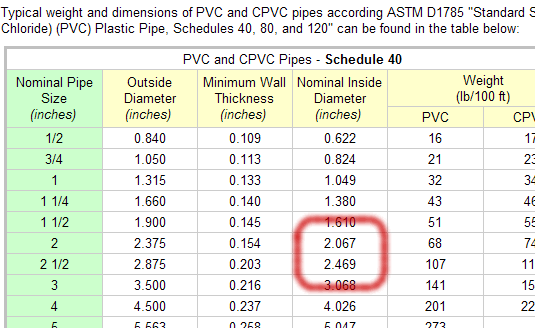
- From the Engineering Toolbox link:

The two closest matches are either the 2" or the 2½" "Nominal Pipe Size" pipe.
- Which size would be the best choice? For any given flow of a fluid such as air, the smaller the cross
sectional area the faster the flow. Also, commonly available and normally stocked sizes are typically
less expensive that sizes that require vendors to place special orders or fabricate the desired size.
A quick check of the web site of one of the local hardware labyrinths (e.g., Lowes or Home Depot, etc.), shows that the typical sizes of "plain end PVC pipe" stocked in the local stores' plumbing sections include ½", ¾", 1", 1 ¼", 1 ½", 2", 3" & 4".
Therefore, in this particular case, our choice would be the nominal 2" PVC pipe which has a nominal inside diameter (ID) of 2.067 inches.
- OK, let's get back to the Rhino drawing...
Draw a circle with a diameter of 2.067" around the point (0,0,1).
- Select both the 2D square and the 2D circle geometry.
 From
the menu, chose Surface->Loft.
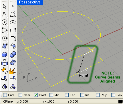
Arrows will appear on each of the selected 2D geometric elements denoting a direction. As the two curves in this example are closed, they can appear facing in any direction. The goal is to get all of the arrows nominally aligned (i.e., all should be oriented in the same direction). Otherwise, the lofted surface will be "twisted" (in a bad way). In the example shown to the right, the arrows are not pointing in the same direction.
 A quick and accurate method of aligning the arrows is to create a point on each 2D geometric element
such that these points all "fall" along a straight line (in one view). Once each loft element has an assigned
point, individually move each curve seam (as required) by clicking on the appropriate curve handle
(at arrow's tail) and dragging it to that curve's particular point
(Hint #1: toggle on the "Point" Object Snap).
Repeat this until all of the curve seam arrows are aligned as shown to the right. (Hint #2: If necessary, flip the direction of the arrow by pressing the 'F' key).
- Once all of the curve seams are aligned, press the <Enter> key to accept and to open the
"Loft Options" window. For this example, set the Style to "Normal" and choose the "Do not simplify" option. Press the [OK]
button to build the lofted surface.
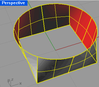
 The
resulting lofted surface will have two open ends. Therefore, you will need to
cap the holes within the surface converting it into a closed polysurface (AKA a solid model).
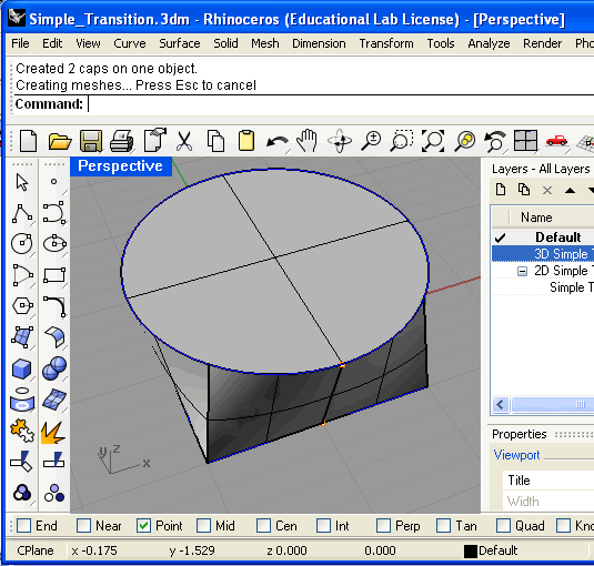
To do this, select the surface (shown to the right). From the Rhino main menu, choose Solid ->Cap Planer Holes. If successful, the command window will display the following message:
"Created 2 caps on one object.
Creating meshes... Press Esc to cancel."
The resultant object will be a closed polysurface which can be manipulated like any solid model.

- Save this simple transistion section model (Use an obvious filename such as Assign3-6a.3dm or Simple_Transition.3dm) as it will be the core geometry you will use in the
next lesson.