- Open the Rhino drawing created and saved in Part A of this unit.
- Save the file under a new filename (Rhino menu: File -> Save As) using an obvious filename such as
Assign3-6b.3dm or Straight_Transition_Plenum.3dm).
- Delete any/all 3D polysurfaces (solids) so that the only geometrical objects in the model file are the
two 2D square & circular elements and their associated points for aligning the loft curve seams.
 Open
the Layer Manager. Create (or rename as required) a layer named "2D Internal Loft Curves" and
place the existing 2D square & circular geometry on this layer. If desired, change the default layer color.
(Note: this lesson will use dark blue for the internal loft curve geometry.) Open
the Layer Manager. Create (or rename as required) a layer named "2D Internal Loft Curves" and
place the existing 2D square & circular geometry on this layer. If desired, change the default layer color.
(Note: this lesson will use dark blue for the internal loft curve geometry.)
-
Create (or rename any existing layers as required/desired) three (3) additional named layers
for organizing loft geometry:
- "Points-Internal Loft"—This layer can be organized as a sub-layer of
the "2D Internal Loft Curves" layer. Additionally, place
the points previously created for aligning the (internal) loft curve seams on this layer.
Finally, if desired, change the default layer color to a lighter shade of the same basic color
used for the 2D Internal Loft Curves layer color. (Note: this lesson will use
light blue for the internal loft points.)
- "2D External Loft Curves." (Note: External loft curve geometry shown in
dark green.)
- "Points-External Loft"—This layer can be a sub-layer of
the "2D External Loft Curves" layer. (Note: External loft points
shown in light green.)
Turn off the 2D External Loft Curves and Points-External Loft layers.
- In order to make a part with constant cross-sections that will fit either over square or circular shapes,
you will need to force Rhino into making the loft geometry hold the desired shape for a short distance,
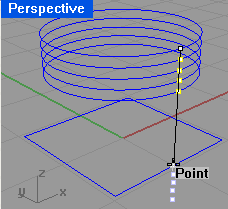
say ½ inch. From the alignment point on the circle object, draw a half inch long vertical line
(i.e., from the point at ABS(0,-1,1) to ABS(0,-1,1.5).
-
Select the new vertical line. Use the "Divide" command to divide the line into four (4) equal segments.
If the MarkEnds toggle was set to "No," place a point on the upper end of the line (for a total of five (5) points).
Change the layer of all of these points to Points-Internal Loft. Delete the line.
-
Using the Point Object Snap, make four copies of the circle object working your way up the 0.5 inch vertical line.
 Select
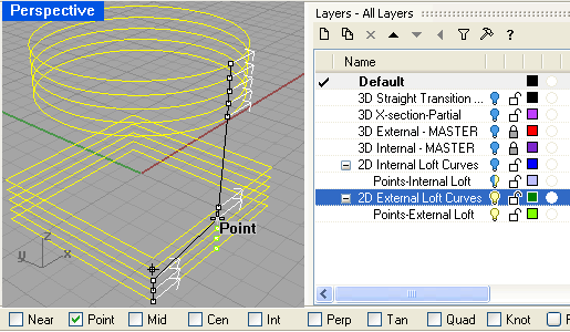
the lower four points. Using the upper-most point as the base, use the Transform->Copy command
to copy this series of four points below the alignment point on the square object. Select
the lower four points. Using the upper-most point as the base, use the Transform->Copy command
to copy this series of four points below the alignment point on the square object.
Using the Point Object Snap feature as you did in the step before, make four (4) copies of the square
object.
Save your work.
- To create the external loft curves, begin by selecting the lowermost circle. Use the "Offset" command
setting the Distance at 0.06 and click outside the circle. Repeat the command for the upper-most
square.
 Establish
an alignment point for each external loft curve by drawing an orthogonal single line from
the corresponding point on the internal loft curve perpendicular to the offset geometry.
After placing a point at each of these intersections, you may delete the two short (0.06) long lines. Establish
an alignment point for each external loft curve by drawing an orthogonal single line from
the corresponding point on the internal loft curve perpendicular to the offset geometry.
After placing a point at each of these intersections, you may delete the two short (0.06) long lines.
- Turn the 2D External Loft Curves & the Points-External Loft layers back ON so you can see them.
Change the new external loft curves and points to their appropriate layers.
-
Using the Point Object Snap and the Transform->Copy command, make two sets of points: one set for the
external loft circle objects and the other set for the external square lofts. Then copy the external circle and square
loft curves using the new external loft points.

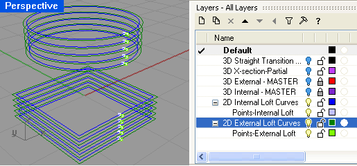
At the conclusion of this step, you should have a (blue) set of internal curves and points nested
within a (green) set of external curves and points as shown above.
- Before creating the lofted surfaces, you need to extend the internal geometry slightly past each end of the
external curves (to ensure that the Solid->Difference command works correctly).
- Turn OFF the 2D External Loft Curves amp; the Points-External Loft layers.
- Select the upper-most internal loft circle and corresponding alignment point.
- Copy these two objects one interval above the last (i.e., go back one point as the base).
- Repeat the last two steps for the lowest square curve and corresponding point.
- Group all similar items together:
- Select & group all of the 2D Internal Loft Curves: 12 total curves.
- Select & group all of the Internal Loft Points: 12 total points layers.
- Turn OFF the 2D Internal Loft Curves & Internal Loft Points layers
AND
Turn ON the 2D External Loft Curves & External Loft Points layers.
- Select & group all of the External Loft Points: 10 total points.
- Finally, select and group all of the 2D External Loft Curves: 10 total curves.
- With the group of ten (10) 2D External Loft Curves selected,
choose the Surface->Loft command.
Use the Point object snap to align the seams; choose the "Normal" style and "Do not simplify"
options and create the External Plenum surface section.

- Select the External Plenum surface and use the Solid->Cap Planer Holes command to turn the open surface
into a closed polysurface (solid). "Push" this new object onto an appropriately named layer (e.g., something
like "3D External Plenum-MASTER."
- Create the Internal Plenum surface by repeating the last two steps for the 2D internal loft curves
and points placing this new solid on another appropriately-named layer.
- Use the Transform->Copy->InPlace option to create copies of both the internal
and external plena and immediately push the copies to the "Default" layer.
- To keep the lofts safe, lock the MASTER layers and turn them both OFF. Also, turn off the layers for all of the
2D loft curves and alignment points.
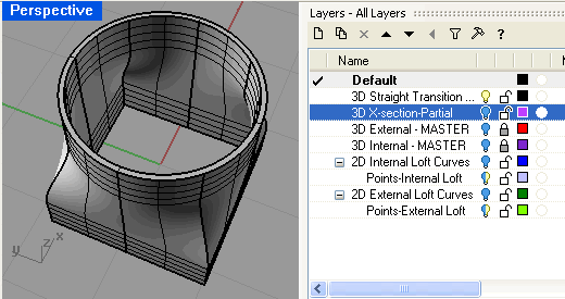
- Select the External Plenum surface and use the Solid->Difference (DeleteInput=Yes option) to create
the final hollow plenum. "Push" this new object onto a layer called something like "3D Straight Transition."

- Saving your work concludes this lesson and prepares you for the
final lesson (Part C).
|
 Open
the Layer Manager. Create (or rename as required) a layer named "2D Internal Loft Curves" and
place the existing 2D square & circular geometry on this layer. If desired, change the default layer color.
(Note: this lesson will use dark blue for the internal loft curve geometry.)
 Select
the lower four points. Using the upper-most point as the base, use the Transform->Copy command
to copy this series of four points below the alignment point on the square object.
 Establish
an alignment point for each external loft curve by drawing an orthogonal single line from
the corresponding point on the internal loft curve perpendicular to the offset geometry.
After placing a point at each of these intersections, you may delete the two short (0.06) long lines.

