- Open the Rhino drawing created and saved in Part B of this unit.
- Save the file under a new filename (Rhino menu: File -> Save As) using an obvious filename such as
Assign3-6c.3dm or 45_deg_Transition_Plenum.3dm).
- Delete all of the 3D polysurfaces (solids) so that the only geometrical objects in the model file are the
2D square & circular elements and their associated points for aligning the loft curve seams.
- In order to ensure that adequate wall thicknesses are maintained throughout the entire plenum, our development strategy
will include the additional six or so processes as follows:
- renaming or creating layers to better organize and understand what is going on (step 5);
- moving both sets of the circular curves (internal and external) and corresponding alignment points away
from the rectangular curves to "open up" the transition area (step 6);
- creating an identified "pivot point" midway between the rectangular and circular curve sets (step 7);
- optionally reorienting the entire 3D model from a nominally vertically data set of curves and alignment points
to a horizontal configuration with the piviot point at the origin (step 8);
- creating a "hybrid" or transitional, cross-sectional closed polyline that is a mix or blend of the square
and the circular geometries for either the internal or the external loft curve set (steps 9 - 10) then
- offsetting the newly created transition closed polyline to match the corresponding external or internal curve
(step 11); and
- rotating around the pivot point both sets of circular curve and paired points (internal and external) to the specificed or
desired angle (e.g., 45°) (step 13) and the pair of internal and external curve/point sets half the desired angle
(e.g., 22.5°) (step 14).
- If you haven't already done so by now, get with the plan, open up the Layer Manager, and create several named layers
to reflect the fact that there will be two sets of closed polylines and/or curves (interior and exterior loft
elements) each with matching alignment point sets. Things can get pretty hairy in 3D modeling; intellegently designed
and purposeful organization will make life much easier and curve selection natural. You've been warned; don't play cute.
- To create more naturally flowing curved sections, we will need to open up the space between the two curve sets.
Otherwise the turning section will be somewhat "pinched" and will not yield the smoothest internal flow passageway.
This can be done easily by first turning on (making visible) both the internal and external curve/alignment point data sets.
Then simply select both sets of circular curves and associated points and then move them all vertically an additional 0.75 to
1.25 inches. This example uses a 1.00 inch additional separation. (Note: Ungrouping the various curve and/or point sets
may be necessary.)
- As the final part will be angled, we need to create an identified "pivot point" midway between the rectangular and circular
curve sets. This will allow you to create the basic geometries in a straight line orientation (very easily) and then rotate the geometric
entities into the desired position. Why work harder than you have to?
A quick and easy way to create this pivot point is as follows:
- turn on Object Snap - Center;
- draw a single line from the center of one of the uppermost rectangles and to the center of the lowermost corresponding circle;
- turn on Object Snap - Mid and place a point on the midpoint of this newly created line; and
- create a new layer called something like "Pivot Point," change the color of the layer as desired, and push the newly created
pivot point to this new layer.
- [While this next multi-part step is purely optional, it really helps. Basically, for those who grew up reading left to right, it makes
the subsequent steps easier to understand.]
If desired, reorient the entire data set by rotating and moving it as follows:
- turn on and unlock all layers;
- use the Edit - Select Objects - All Objects command [Ctrl + A] to select all visible geometric entities;
- activate the Front view and then use the Transform - Rotate command to rotate the entire data set around
the origin (i.e., around the Y axis) so that the nominal axis of the transistion section runs horizontally ;
- use the Transform - Move command, snap on the pivot point and move the entire data set to the origin (Absolute 0,0,0); and
- turn off the appropriate layers.
At the conclusion of Step 8, your relocated curve/point data sets and the centrally located pivot point should appear as follows:
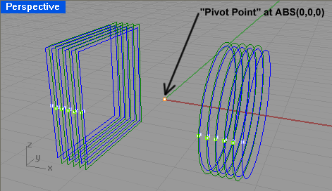
- During the next three steps (9 - 11), we will create a pair of "hybrid" or transitional, cross-sectional closed polylines
centered around the pivot point. The overall purpose of these transititional cross-sectional geometries—
blending the rectangular and circular geometries—is to to ensure that both the interior and exterior
surfaces remain identical and parallel thoughout the entire part by maintaining control of the loft curve in the
"magical" transitional section (i.e., we don't have to trust the software to behave in the middle parts where
it is making stuff up).
Choose either the internal or external lofting curves to work with (this example uses the internal) and use
the Layer Manager to turn off the unwanted curves and points.
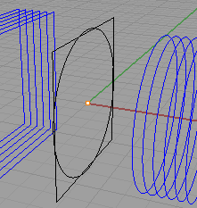 Use the following process to
copy the geometric data to the pivot point: Use the following process to
copy the geometric data to the pivot point:
- If necessary, select the lofting curve data set(s) and use the Ungroup command so that you
can select individual curves;
- Using Snap - Center, copy one rectangular curve and place place it (Snap - Point) at the pivot point;
- Likewise, using Snap - Center, copy one circular curve and place it (Snap - Point) at the pivot point;
- To simplify things, "clear the decks" by pushing these two entities to the default layer and turn off everything else;
- Select both entities and in the appropriate plan view, use the Edit - Trim command to remove
the inside line/curve segments (as shown below);
- Select all of the curves making up this hybrid geometry and use the Join command to create
a closed, watertight polyline. Upon completion of this command, you should get the reassuring
"8 (or 12) curves joined into one closed curve";
- If desired, you can also "round off" the four sharp corners by using the Fillet command.
In this example, a fillet radius of 0.5 inches was chosen.
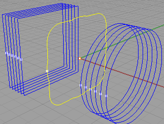 Push
this new entity from the default layer to the desired loft layer; turn that layer back on as
well as the layer for the lofting alignment points; and then Push
this new entity from the default layer to the desired loft layer; turn that layer back on as
well as the layer for the lofting alignment points; and then- Create an appropriately placed alignment point (similarly oriented as the others of this curve set) and
push this point to the appropriate points layer. When completed, the newly created transition section
will appear similar to that shown.
- Use the Offset command to create the corresponding external (or internal) transitional polyline
at the appropriate offset distance. (Hint: Create the appropriately trimmed orthogonal
geometry and use the Analysis - Length command if you cannot remember what the original offset
distance was). Push the new geometric entity to the appropriate layer and turn that layer on and
the other one off. Create an appropriately located alignment point and push it to the appropriate layer.
- If desired, you can select and group the various curves to make the lofting process a bit less tedious.
Before you do this, please remember that the order of selection is very important when using lofts.
- Use the Layer Manager to turn on the internal curve set and turn off the visibility of the external curve set.
- Within the Front or Perspective view and working from right to left, select each of the internal
circular loft curves and Group them.
- For the moment, ignore the transition element.
- Working in the same direction (right to left) as before, select the internal rectangular loft
curves and Group them.
- Note: Do not make a "group of groups" just yet... the curve and point sets need to be rotated into place first!
Repeat this process for the external curve set creating a circular group and a rectangular group.
- It is time to make the now straight curves "bend." While both the internal and external curve/point pairs will be
rotated the full desired amount (this step), the transition curve/point pair will be rotated only half of that
amount (in Step 14).
- Turn on both the external and internal loft curve/alignment point data sets (typically four (4) layers.
- Select the circular curves and point sets.
- Switch to the Front view.
- Rotate both sets of curve/point pairs around the pivot point (in this case, ABS X0, Y0, Z0)
to the specified or desired angle (e.g., 45°).
Note: For those situations where a geometric modification is not so obvious,
say if the design requires an angle of 36.85°, use the File - Notes command to bring up a handy text window to
document the exact design criteria. This type of internal documentation can be incredibly helpful...especially
a year or two (or even six days) after you finish a drawing.
- The transitional curves/alignment point pairs should now be rotated as follows:
- Switch to the Front view.
- Select both transitional curves and alignment point pairs.
- Rotate both sets of curve/point pairs around the pivot point (X0, Y0, Z0)
to the one half of the angle of the previous step (e.g., 22.5°).
- From here on out, the lofting process used previously
(Assignment 3-6b) may be pretty much followed (from Step 16 onward).
The only major change in the process is that when the "Loft Options" window pops up, under
the "Style" parameter, choose the "Loose" value. In this case, this parameter will provide the best
(i.e., smoothest) transistion without kinking.
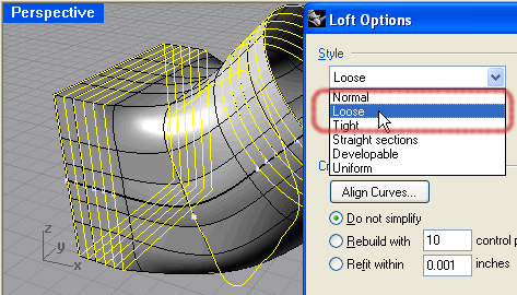
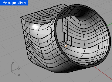
- When completed, your 45° transition section should look something like this:
- If desired, you can make an In-place Copy of the transition section and with a few judiciously placed
cutting planes ensure that the interior and exterior surfaces are parallel (no thick or thin areas). An example
of these cross-sectional inspection cuts can be seen on the bottom of the
Assignment 3-6 Home page.
- Saving your work concludes this lesson.
|

